

Suspension control apparatus
A control device and suspension technology, applied in suspension, elastic suspension, transportation and packaging, etc., can solve problems such as increasing the cost of sensors, and achieve the effect of reducing the number of sensors
- Summary
- Abstract
- Description
- Claims
- Application Information
AI Technical Summary
Problems solved by technology
Method used
Image

Examples
no. 1 example
[0038] First, the suspension control device of the first embodiment includes: a damping force adjustable shock absorber and a control device for controlling its damping characteristics. The shock absorber is installed between the vehicle body and the wheel, and adjusts the damping characteristic according to an external command. It is characterized in that the control device includes: a first up and down motion calculator for calculating the up and down motion of a first point set at an arbitrary position of the vehicle body, and a roll motion estimator for estimating the roll motion of the vehicle body , a pitching motion estimator for estimating the pitching motion of the vehicle body, a vertical motion calculator for each part calculating the vertical motion of each part of the vehicle body based on the vertical motion, the roll motion, and the pitching motion, The up and down movement of each part is calculated and the command is sent to the controller of the damping force ...
no. 2 example
[0059] Below, according to Figure 1-6 The suspension control device in the second embodiment of the present invention will be described more specifically.
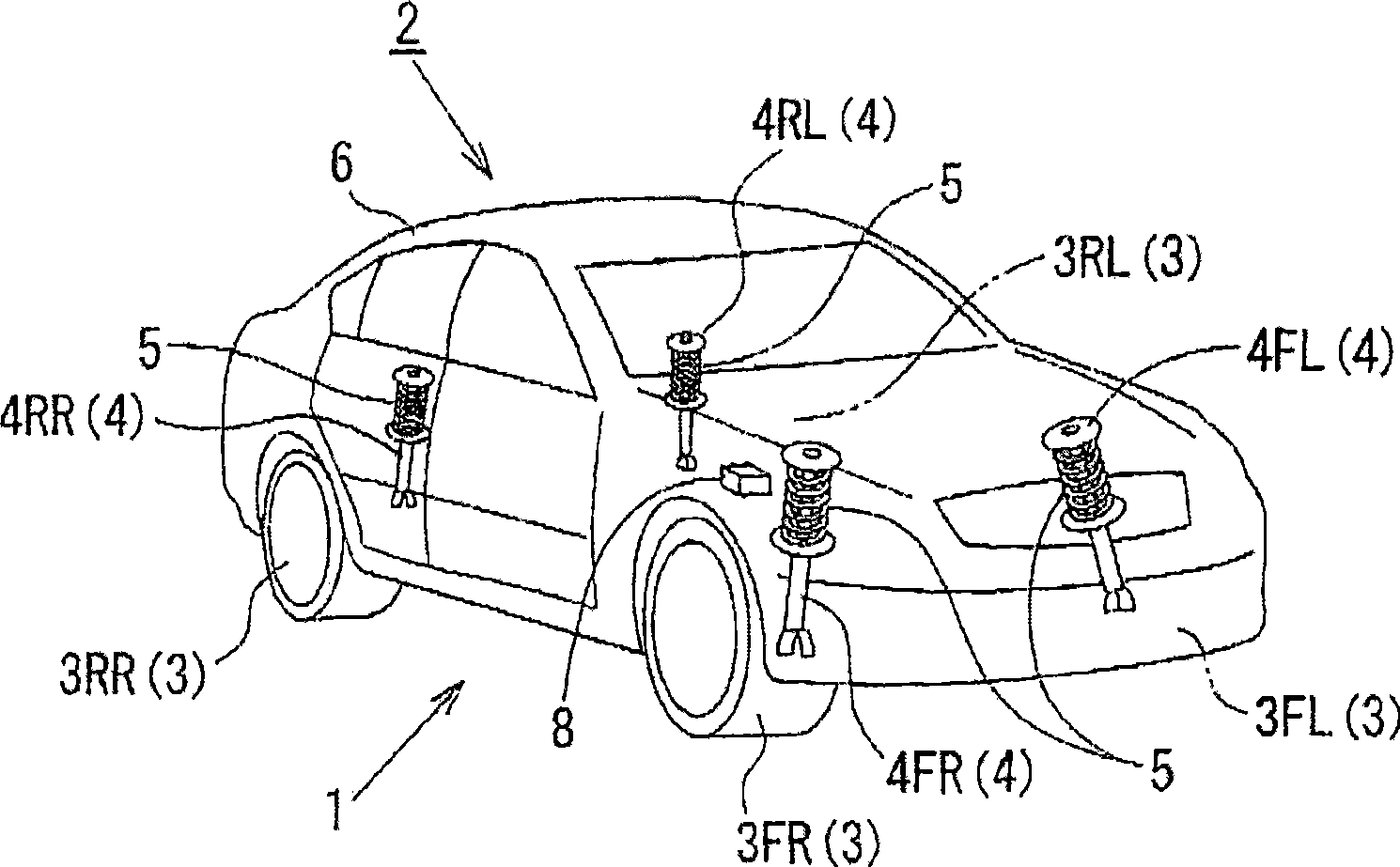
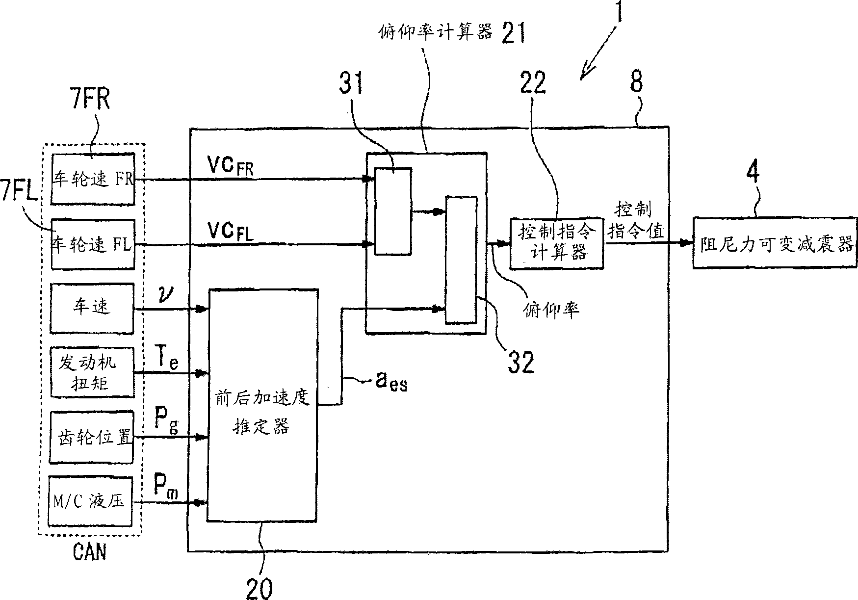
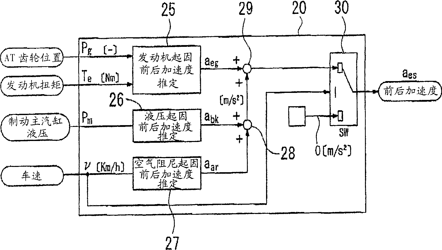
[0060] figure 1 It is a schematic perspective view showing the component layout of a vehicle provided with a suspension control device in a second embodiment of the present invention. figure 2 is for illustration figure 1 Block diagram of the control functions of the control unit shown. image 3 yes means figure 2 Block diagram of the fore-aft acceleration estimator. Figure 4 is for illustration image 3 A block diagram of the control function of the front-rear acceleration estimation unit caused by the medium engine. Figure 5 is used to illustrate the image 3 Block diagram of the control function of the front-rear acceleration estimation unit due to the middle brake fluid pressure. Figure 6 is used to illustrate the image 3 Block diagram of the control function of the front-rear acceleration estimation pa...
no. 3 example
[0151] Such as Figure 8 As shown, it is also possible to use a control device 8B in which, in order to replace the vertical acceleration estimator 51 and the roll rate calculator 52 for calculating (estimated) the roll rate of the vehicle body 6 used in the above-mentioned second embodiment, a device for calculating The first vertical acceleration calculator 61 of the vertical acceleration at the first point of the vehicle body 6 and the second vertical acceleration calculator 62 for calculating the vertical acceleration of the second point of the vehicle body 6; The up and down motion calculator 53 for calculating the up and down movement of each part of the vehicle body 6 is also provided with a vertical motion calculator 53A. The up and down motion calculator 53A calculates the vertical acceleration and pitch rate of the first and second points to calculate the vertical motion of the vehicle body 6. Each part moves up and down.
[0152]According to the third embodiment, t...
PUM
 Abstract
Description
Claims
Application Information