Child-preventing security igniting gun

A kind of ignition gun and child-proof technology, applied in the field of ignition guns, can solve the problems of unbalanced force on the cross rod, poor ignition reliability, false ignition, etc., and achieve the effect of simple and compact structure and high reliability

Inactive Publication Date: 2009-07-08
宁波飞翔电子设备有限公司
View PDF2 Cites 8 Cited by
  • Summary
  • Abstract
  • Description
  • Claims
  • Application Information

AI Technical Summary

Problems solved by technology

However, because of its ease of operation, and its shape, function, and use are all like a toy, it is easy to be accidentally ignited by children playing, thereby causing safety hazards
[0003] In order to overcome the above defects, various ignition guns with safety devices have appeared, and most of the safety devices can automatically reset, that is, when the ignition gun is not used or after use, its safety device is always in the "off" automatically. At this time, only the ignition trigger is pressed but the ignition gun that cannot be ignited due to insufficient ignition stroke is designed, such as Chinese Patent No. 01246127.X "A Kind of Child Safety Ignition Gun", 02260474. "Ignition Gun" is such a solution. Although it can press the ignition trigger, it cannot be ignited by fully pressing the ignition stroke, so it overcomes the above defects well. However, in the process of use, the patent number is 01246127.X The cross rod used in "A Child Safety Lighting Gun" is a single piece with a large volume. When moving between the back and abdomen in the handle, it only relies on the guide groove on the side wall of the handle, so it will not move during the movement. Shake and become unstable between the side walls of the handle, resulting in the defect of poor ignition reliability; and when installing, because the return spring is against the upper part of the vertical rod, the force on the cross rod is unbalanced, and it is easy to make it out of the installation position. It makes installation time-consuming and tro...

Method used


Image

  • Child-preventing security igniting gun
  • Child-preventing security igniting gun
  • Child-preventing security igniting gun

Examples


Embodiment 1

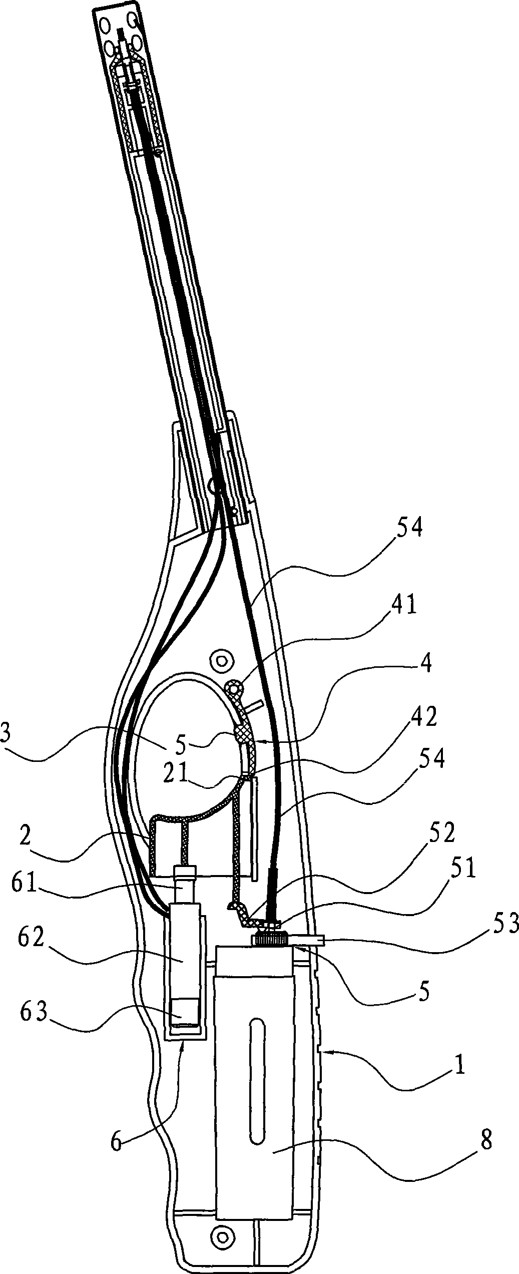
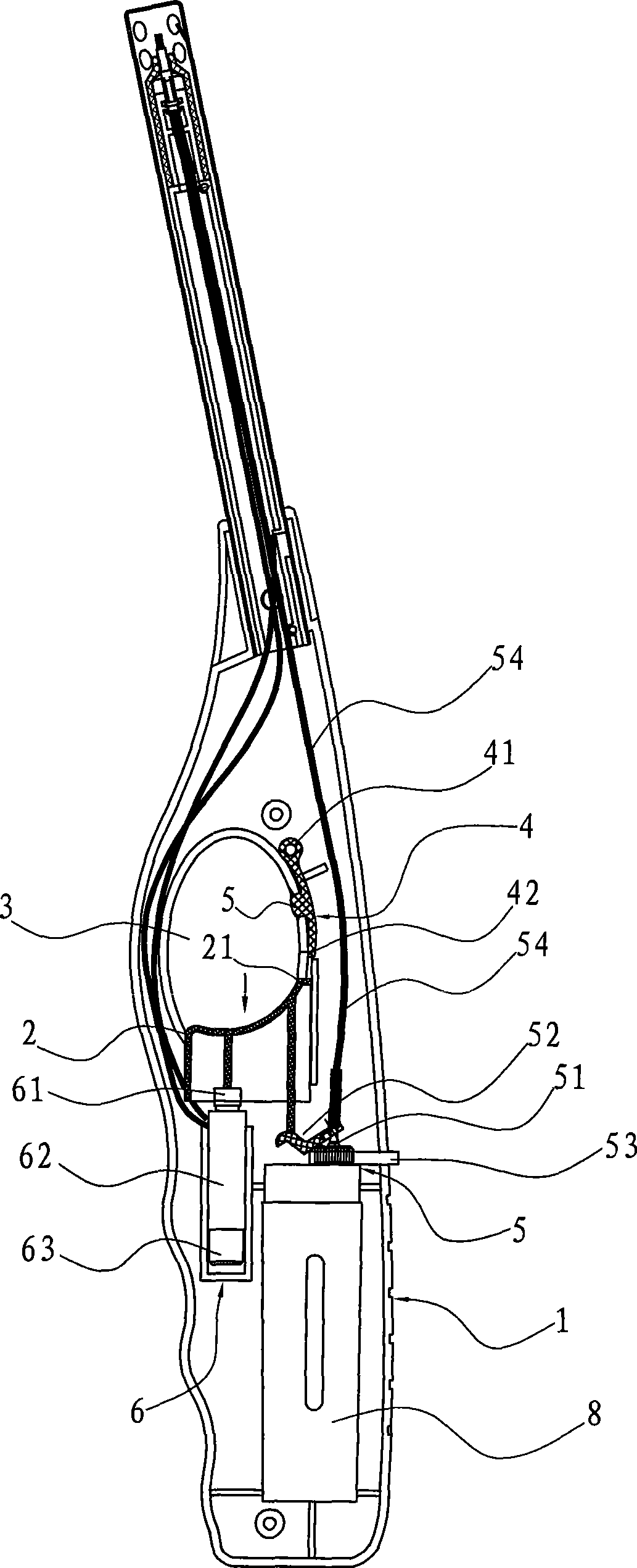
[0031] Such as Figure 1~3 As shown, the ignition gun includes a handle 1 that can be held and an ignition barrel that extends outwards. The handle 1 and the ignition barrel in this embodiment have substantially the same shape and are integrated. Box 8 and its gas valve device 5 and piezoelectric ignition device 6, wherein the gas valve device 5 includes a gas outlet needle 51 and a rocker 52 connected to the gas outlet needle 51 at one end, and the gas is sent through the gas delivery hose 54 connected to the gas outlet needle 51. To the nozzle of the ignition gun, the piezoelectric ignition device 6 includes a piezoelectric cap 61, a piezoelectric body 62 and a piezoelectric copper anvil 63, which are used to generate voltage and cause a discharge spark at the nozzle of the ignition gun through a wire; There is an adjusting button 53 for adjusting the size of the fire pit;

[0032] The ignition trigger 2 is arranged on the abdomen of the handle 1, and partly exposed outside...

Embodiment 2

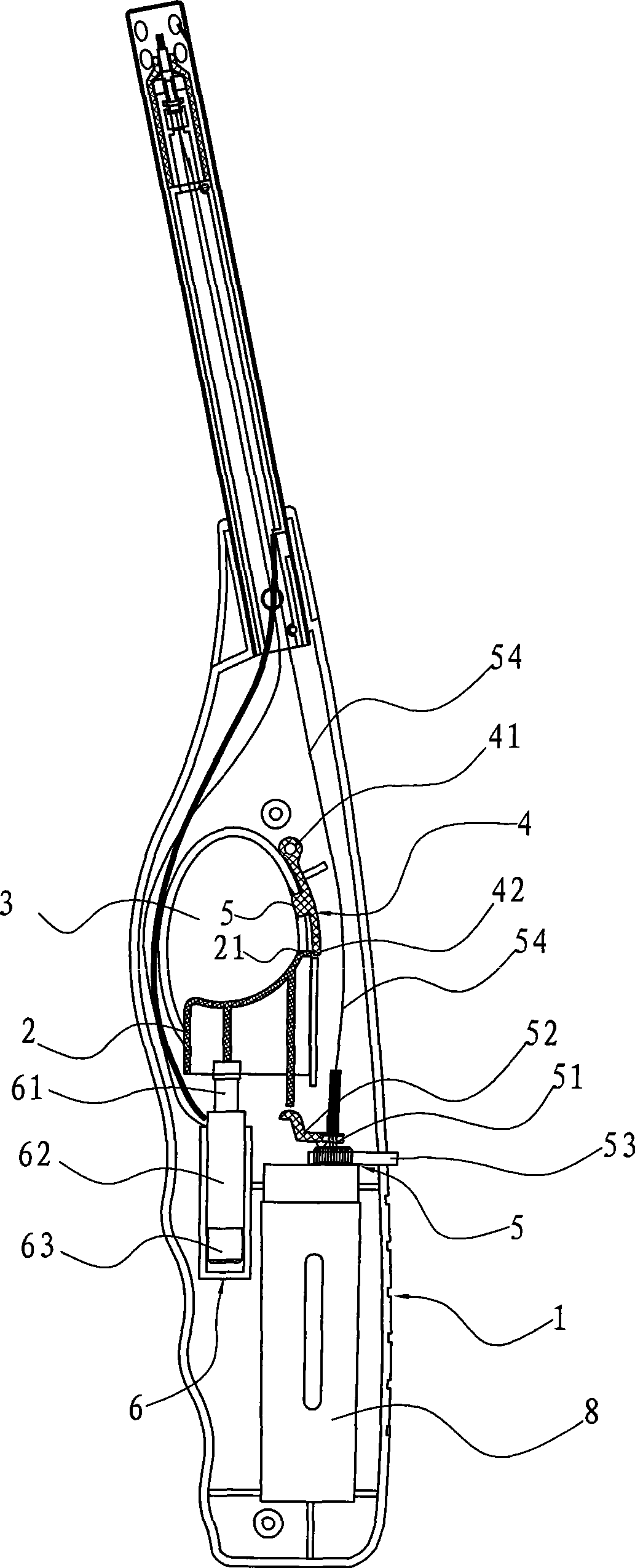
[0038] Such as Figure 4 As shown, the difference from Example 1 is that see Figure 4 As shown, the above-mentioned resettable blocking member 4 is arranged below the ignition trigger 2, and the lower end of the ignition trigger 2 is provided with a limit protrusion 22, which is reset under the reset mechanism of the piezoelectric device after the ignition trigger is used for ignition. At this time, the free end of the elastic member 4 is in contact with the limit protrusion 221 at the lower end of the ignition trigger 2 under the action of its own elastic force, so that the ignition trigger 2 cannot be completely reset automatically.

[0039] And safety switch 5 is arranged on below the middle part cavity of the handle, and part is exposed to the cavity below the middle part of the handle.

[0040] Its working principle is the same as that of Embodiment 1, and will not be repeated here.

Embodiment 3

[0042] Different from Embodiment 1, the resettable blocking member 4 is not an integral elastic member, but a part of the elastic member, which includes a limiting member 4a and an elastic reset member 4b, see Figure 5 As shown, and the limiting part 4a and the elastic reset part 4b are one piece, the elastic restoring part 4b is made of an elastic sheet, the first end of the elastic restoring part 4b is connected with the free end 412 of the limiting part 4a, and the elastic restoring part The second end of 4b is against the inner wall of the handle, and forces the limiting member 4a to have a tendency to move downward relative to the ignition trigger; one end 411 of the limiting member 4a is rotatably arranged in the handle, and the other free end 412 is in the reset state and is in contact with the ignition trigger. The upper end of trigger 2 is offset. Its working principle is the same as that of Embodiment 1, and will not be repeated here.


PUM


Abstract

The invention relates to a child-resistant safety ignition gun, which comprises a handle for holding and a gun barrel extending outwards, wherein a fuel gas box, an air valve device thereof and a piezoelectric ignition device are arranged in the handle; and an ignition trigger for driving the piezoelectric ignition device to ignite and driving the air valve device to release air is arranged on the abdomen of the handle and part of the ignition trigger is exposed out of the handle. The child-resistant safety ignition gun is characterized in that a protecting device which makes the ignition trigger not restore completely after finishing using the ignition gun is also arranged in the handle, wherein the protecting device comprises a safety switch and a restorable blocking piece, wherein part of the safety switch is exposed outside a mounting hole corresponding to the handle; and the restorable blocking piece which can overcome restoring force to move under the drive of the safety switch, can resist the ignition trigger in the restoring state so that the ignition trigger cannot restore completely, and generate displacement and release the limitation on the ignition trigger under the drive of the safety switch so that the ignition trigger is restored. Besides, the child-resistant safety ignition gun has the advantages of simple and compact structure and high reliability.

Description

technical field [0001] The invention relates to an ignition gun, in particular to an ignition gun which can prevent children from mistakenly igniting because the user only presses the ignition trigger but cannot normally ignite. Background technique [0002] Existing igniter generally comprises a handle that can be held and a igniter tube that extends outwards from the handle upper end, is provided with gas box and its gas valve device, piezoelectric ignition device and ignition trigger in the handle, The box is filled with liquefied combustible gas. When in use, press the ignition trigger, and the gas valve will open accordingly. At the same time, the piezoelectric ignition device will generate electric sparks at the nozzle of the ignition gun through the wire, and ignite the combustible gas delivered to the nozzle of the ignition gun through the gas delivery pipe. Gas, at this time, if you keep pressing the ignition trigger and don't let go, you can maintain a burning flam...

Claims


Application Information

Patent Timeline
IPC IPC(8): F23Q2/16F23Q2/34
Inventor 茅雪飞李东良
Owner 宁波飞翔电子设备有限公司
Why Eureka
Try Eureka