Method of railway wireless environment path loss index estimation
A path loss, wireless environment technology, applied in wireless communication, radio wave measurement system, transmission monitoring and other directions, can solve the problem of not necessarily applicable and high cost
- Summary
- Abstract
- Description
- Claims
- Application Information
AI Technical Summary
Problems solved by technology
Method used
Image
Examples
Embodiment 1
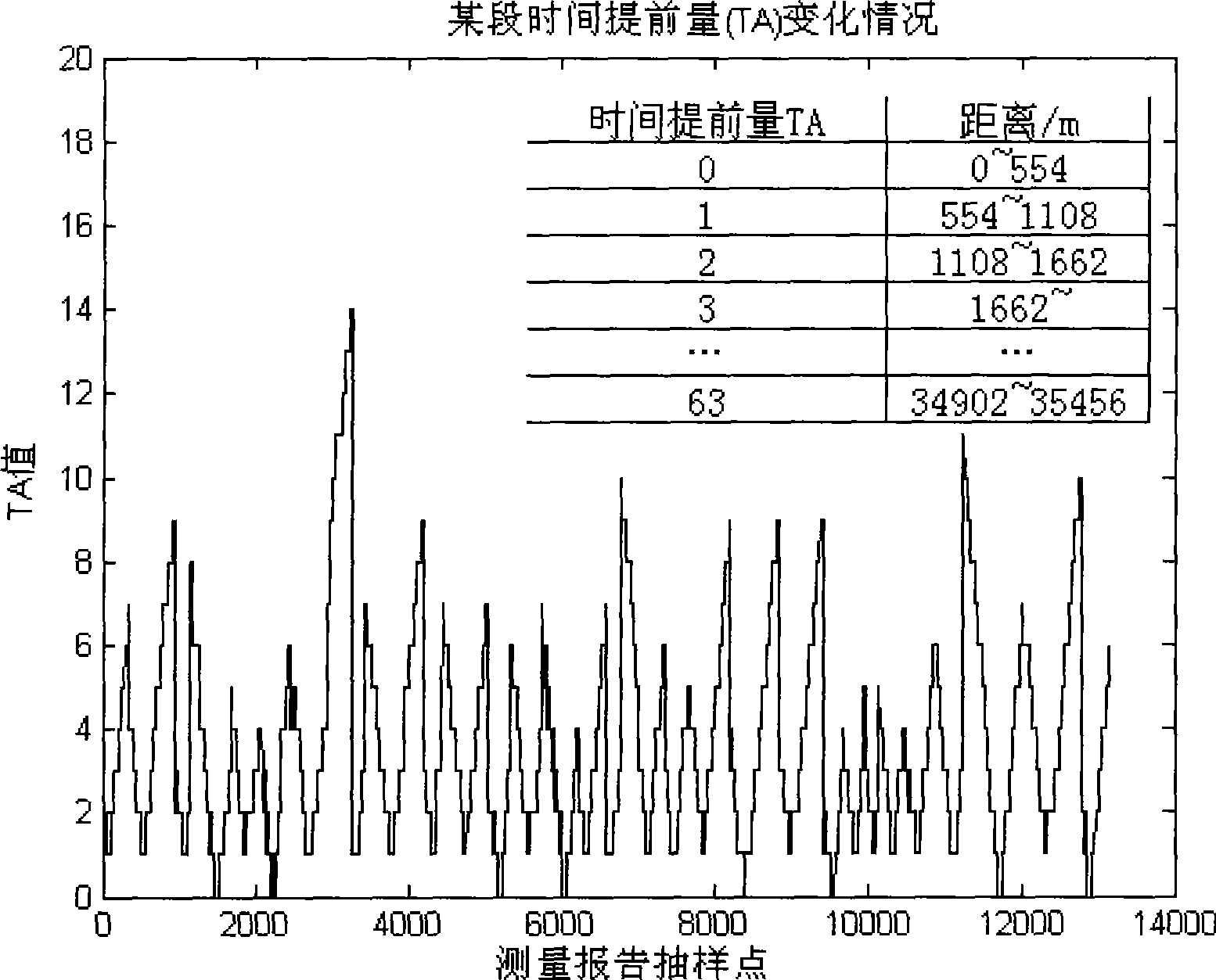
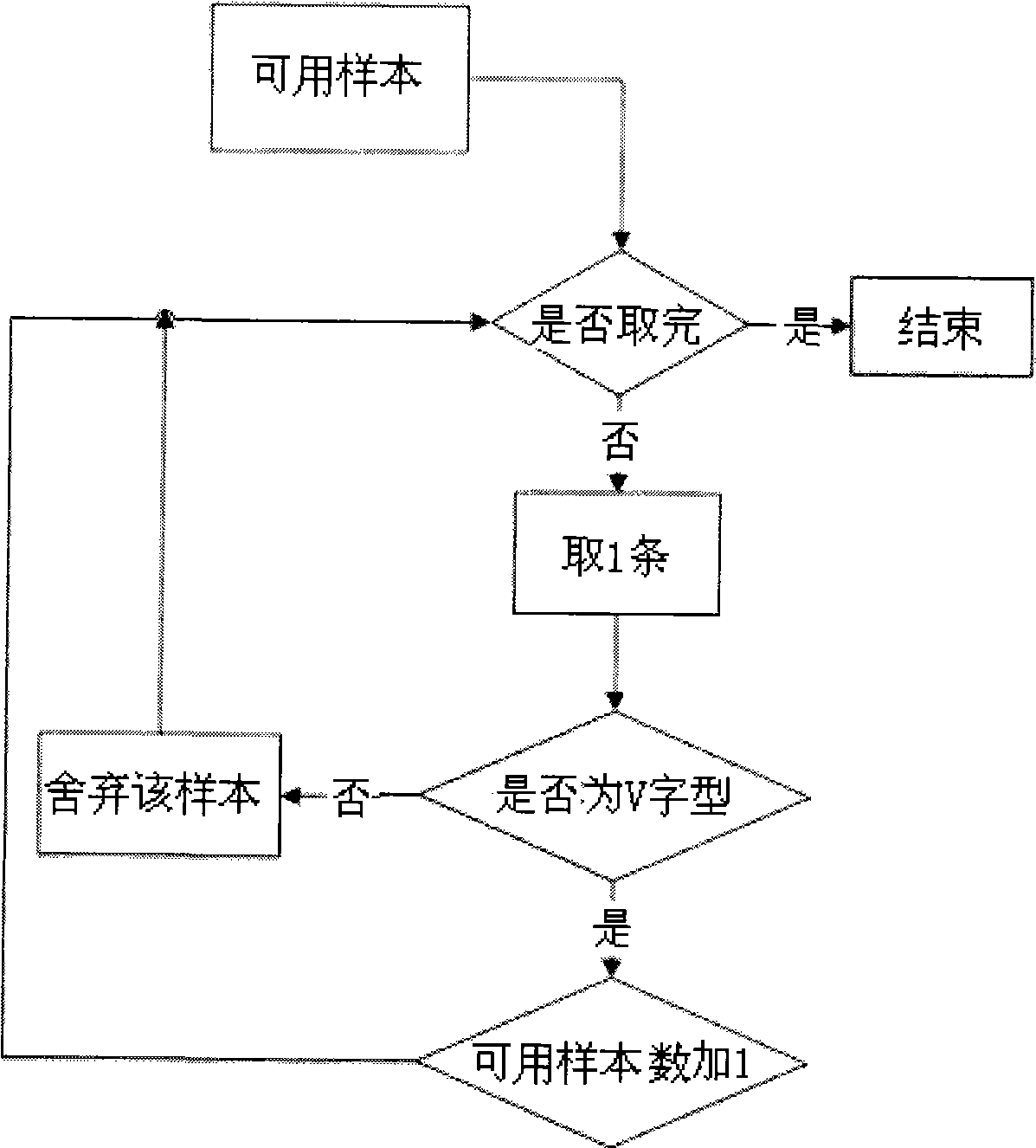
[0065] Embodiment 1: According to the classical wireless propagation theory, the strong-scale fading of the wireless receiving signal field has a logarithmic linear relationship with the distance, and the slope of the straight line is the path loss index. Since the radial path selection process is omitted, it is necessary to judge whether the railway line satisfies this log-linear relationship. Verify by measuring the timing advance in the report: for the time division system, the timing advance is used to resist signal delay. As the distance between the mobile station and the base station changes, the transceiver gradually instructs the mobile station to send in advance. It varies from 0 to 233 microseconds. Generally, the time advance between stations is V-shaped, and the whole line is zigzag, which means that the train basically moves radially along the base station; if the time advance between stations on the whole line is trapezoidal, it means that the train runs with a l...
Embodiment 2
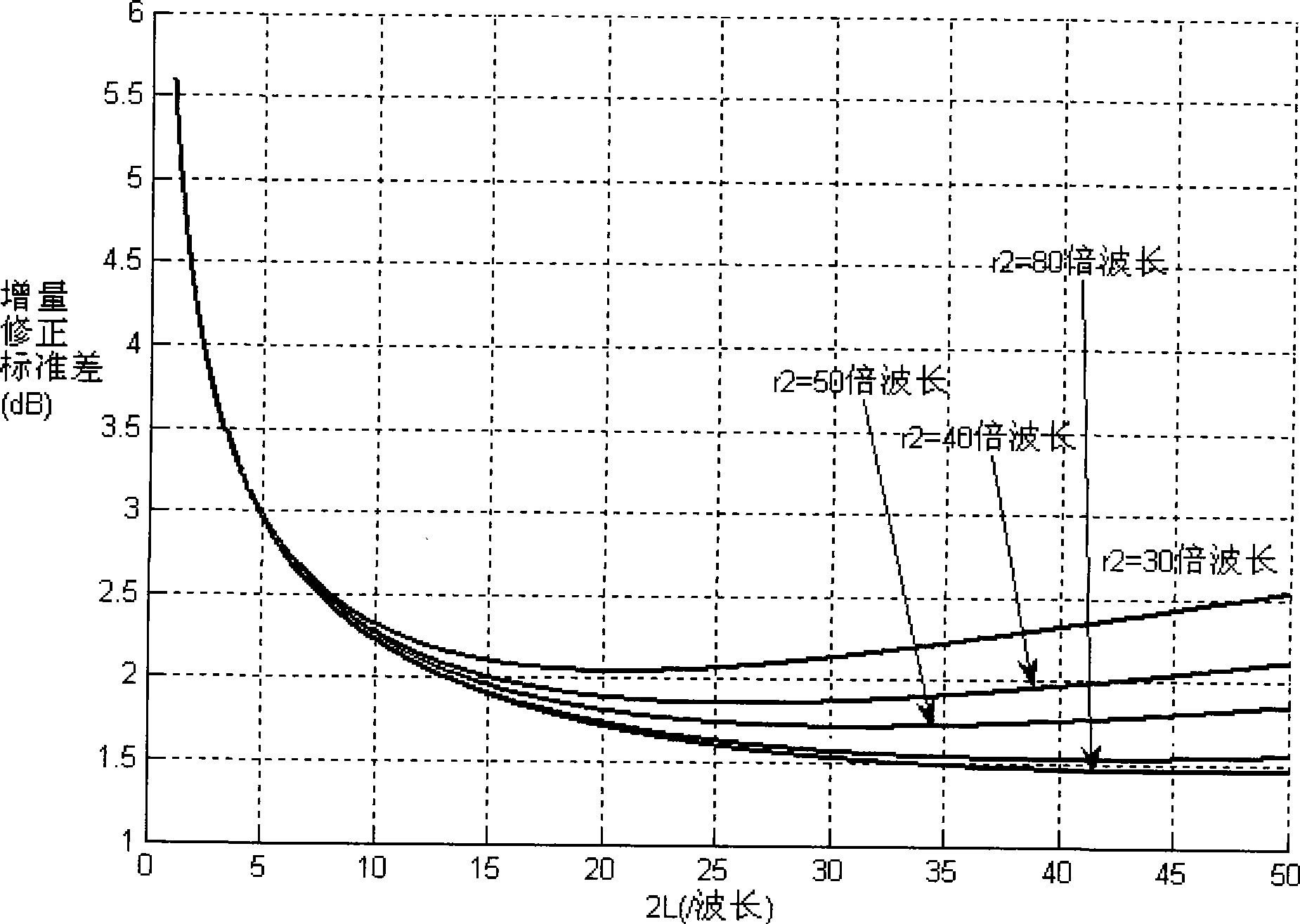
[0073] Embodiment 2: After receiving the effective measurement report samples, it is necessary to determine the statistical interval through the wedge diffraction model, and then obtain the sampling interval for cubic spline sampling. The process of determining the sampling interval is given as follows:
[0074] Step 1: Determine which wedge diffraction model to apply according to the terrain relief factor defined by the International Union of Railways. If the factor is less than 2, apply the single wedge diffraction model; if the factor is not less than 2, apply the double wedge diffraction model to determine the statistical interval;
[0075] Step 2: If it is a single-wedge diffraction model, parameters such as the height of the single-wedge obstacle, the service frequency of the cell base station, and the average effective distance between the train and the obstacles around the track must be obtained to determine the Fresnel in the single-wedge diffraction model ear diffra...
Embodiment 3
[0081] Embodiment 3: Embodiments 1 and 2 lay the foundation for sample data processing. The data processing flow of embodiment 3 is as Figure 4 shown. The following are several steps to obtain the path loss index by applying the numerical method:
[0082] Step 1: According to the GPS positioning information of the train or the kilometer mark information of other interfaces, store the samples with a number of not less than 5 in an array, and perform strict time alignment operations. Since the interval of GPS positioning information or mileage mark information is longer than the interpolation interval, it is necessary to manually fine-tune the comparison after the general alignment. The comparison criterion is: every 20 sampling points are compared once, and there are many comparison sampling points More than 10, the total deviation is less than 20dB, it can be considered as time aligned;
[0083] Step 2: In order to avoid the phenomenon of high-order ill-conditioned interpo...
PUM
 Abstract
Description
Claims
Application Information
 - R&D
- Intellectual Property
- Life Sciences
- Materials
- Tech Scout
- Unparalleled Data Quality
- Higher Quality Content
- 60% Fewer Hallucinations
Browse by: Latest US Patents, China's latest patents, Technical Efficacy Thesaurus, Application Domain, Technology Topic, Popular Technical Reports.
© 2025 PatSnap. All rights reserved.Legal|Privacy policy|Modern Slavery Act Transparency Statement|Sitemap|About US| Contact US: help@patsnap.com


