Method for automatically processing pipe fitting and equipment thereof

A technology for automatic processing and pipe fittings, applied in the field of automatic processing equipment, can solve problems such as the difficulty of fixing the threaded rod, the inconvenience of automatic pressing into the wear-resistant sleeve, and the difficulty of accurately controlling the feeding amount of the pipe fittings, so as to save labor costs and improve work. The effect of efficiency

Inactive Publication Date: 2009-07-15
庄添财
View PDF0 Cites 26 Cited by
  • Summary
  • Abstract
  • Description
  • Claims
  • Application Information

AI Technical Summary

Problems solved by technology

[0003] The connecting rod is processed by an automatic method. Since a series of punching holes are required on the raw material pipe, and in order to prevent the raw material pipe from being deformed during punching, a piercing rod is placed inside the pipe fitting. According to the general pipe fitting processing method, later Feed forward, punch a hole at the front end of the pipe fitting and press it into the wear-resistant sleeve. There are difficulties in fixing the piercing rod: if the piercing rod is inserted from the front end of the raw material pipe, it will leave a hole on the inner wall of the pipe fitting after punching. Burrs, when the pipe moves forward, the friction between the piercing rod and the gradually increasing burrs on the pipe will inevitably increase, so it is not easy to accurately control the feeding amount of the pipe. In addition, the piercing rod is at the front end of the raw material pipe It is not easy to automatically press into the wear-resistant sleeve; if the through-hole rod enters through the sleeve from the rear of the raw material pipe, the through-hole rod cannot be fixed because the raw material pipe is too long
[0004] Due to the insurmountable technical difficulties mentioned above, wear-resistant sleeves and end caps are currently pressed onto the short pipe by hand, and the low efficiency of manual work has been unable to meet the growing market demand.

Method used


Image

  • Method for automatically processing pipe fitting and equipment thereof
  • Method for automatically processing pipe fitting and equipment thereof
  • Method for automatically processing pipe fitting and equipment thereof

Examples


Embodiment Construction

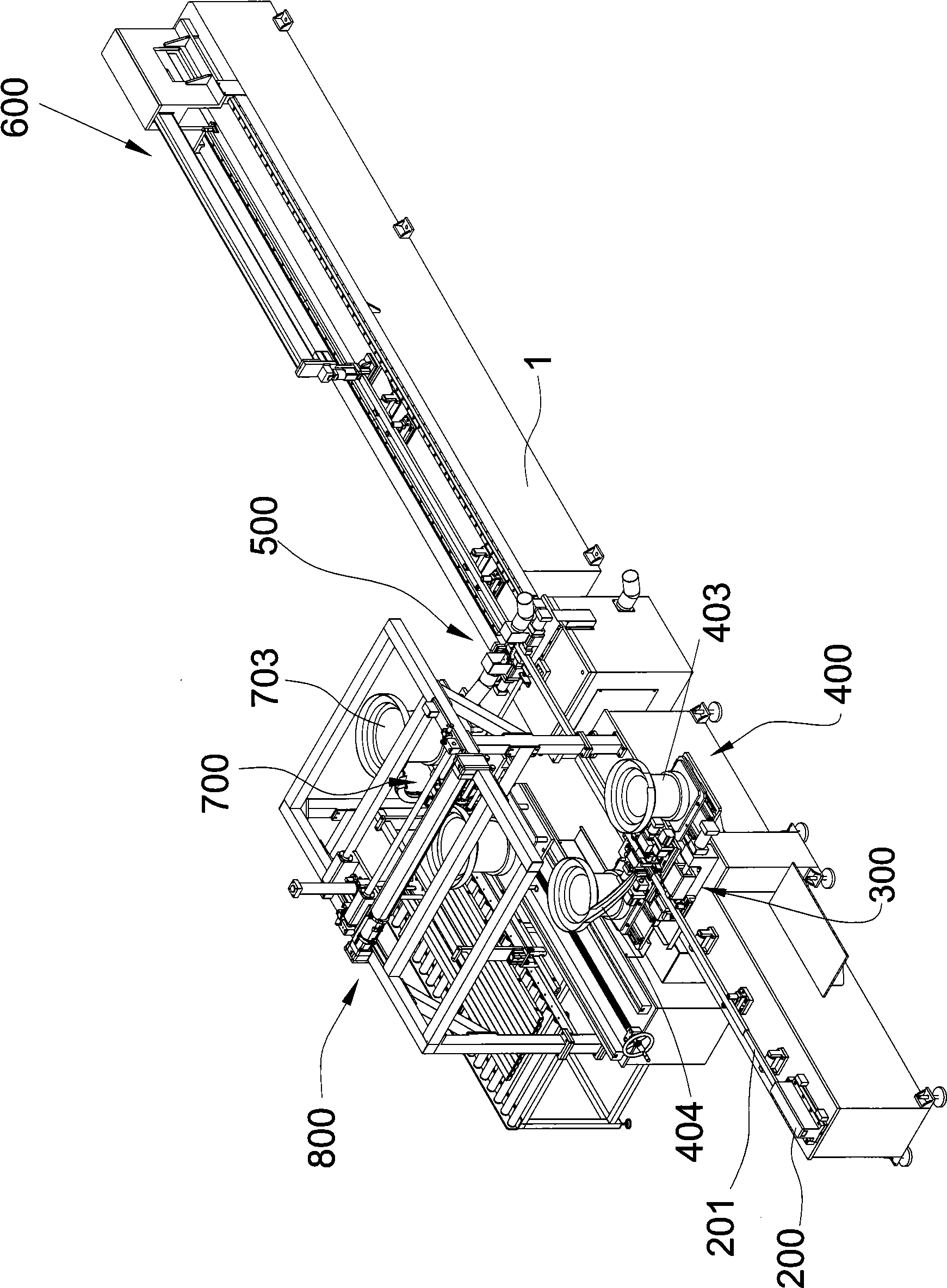
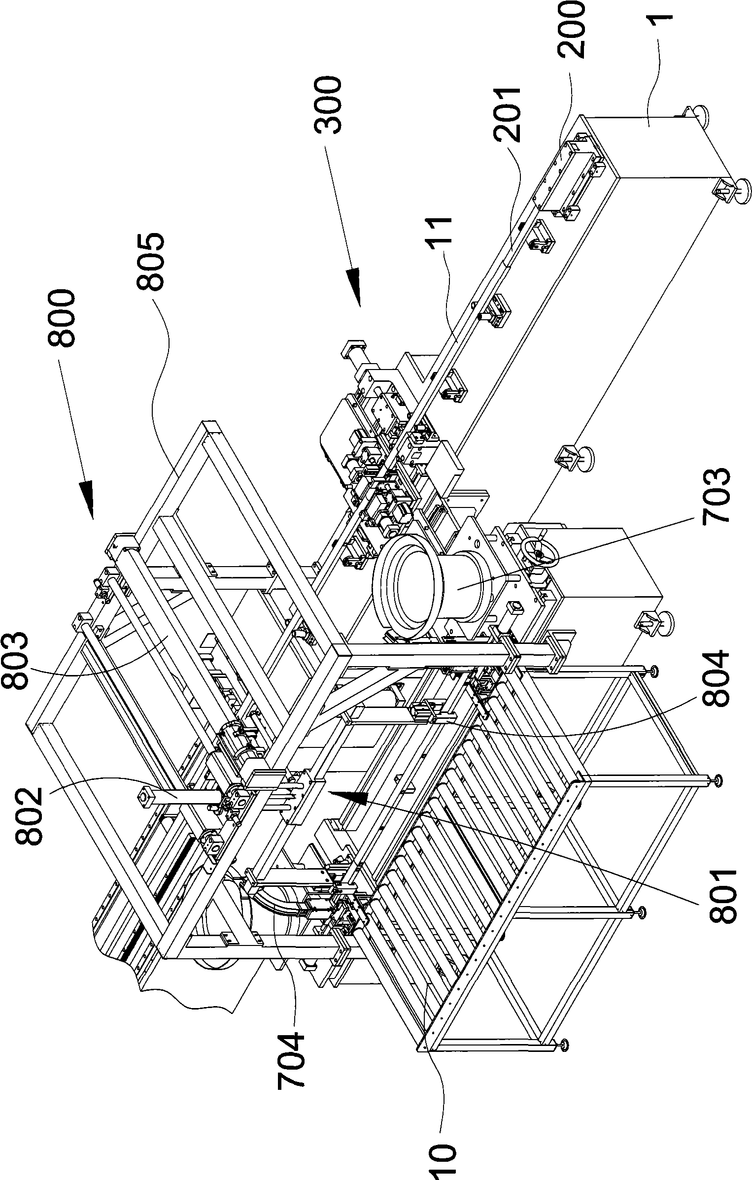
[0043] Attached below figure 1 to attach Figure 7 The content of the present invention will be described in detail.

[0044] An automatic processing equipment for pipe fittings, which includes a workbench 1, on which a core-through rod 201, a punching mechanism 300, a wear-resistant sleeve pressing mechanism 400, a cutting mechanism 500, a clamping mechanism, and The feed mechanism 600 for moving the workpiece forward or backward, the piercing rod 201 extending from the front end of the workbench 1 to the punching mechanism 300;

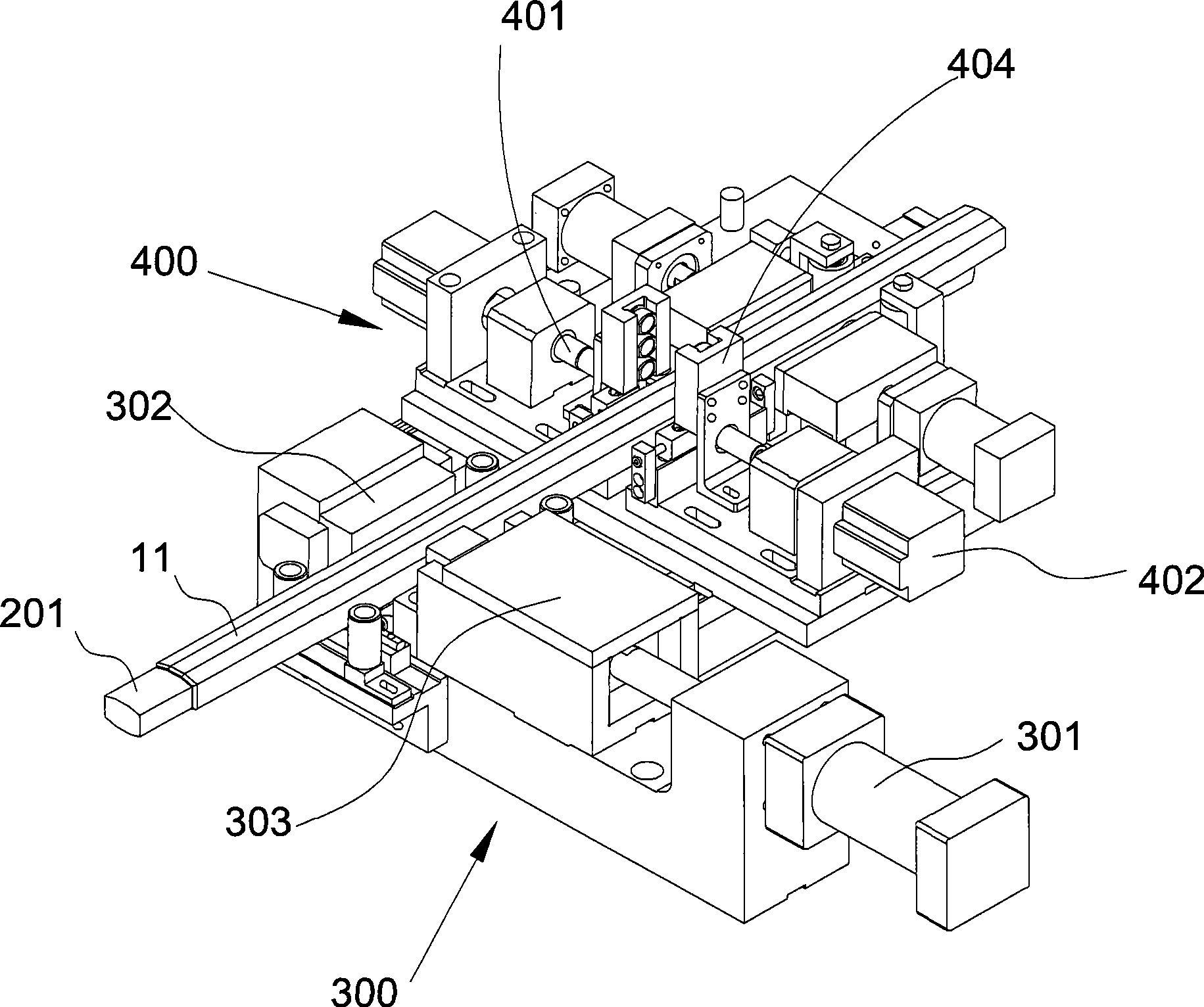
[0045] The punching mechanism 300 includes an oil cylinder 301 fixedly connected to the workbench 1, a U-shaped positioning die 302 and a punch 303 provided with a punching needle thereon, and the positioning die 302 is fixedly connected to the piston rod of the oil cylinder 301 superior;

[0046] The wear-resistant sleeve press-in mechanism 400 includes a wear-resistant sleeve automatic feeding device, a wear-resistant sleeve press head 401, and...


PUM


Abstract

The invention relates to an automatic pipe fitting processing method and a device designed for implementing the method. The device is mainly used for punching a long raw material pipe, pressing an abrasion resistant sleeve into each punched hole, cutting out short pipes with specific lengths from the long raw material pipe and pressing end covers to both end parts of each short pipe. The method comprises the following steps: the raw material pipe penetrates the outer side of a piercing rod from the back to the front, a position to be punched within an area to be cut is ensured to be positioned in the front of the punching position, a first hole is punched on the area to be cut on the raw material pipe, then the long raw material pipe is retreated to move the first punched hole to the pressing position of the abrasion resistant sleeve, then the abrasion resistant sleeve is pressed into the first punched hole, the next hole is punched on the raw material pipe, and the operation is repeated till all holes within the area to be cut are completely punched and the abrasion resistant sleeves are all completely pressed; the raw material pipe is cut to obtain short pipes till the raw material pipe is entirely and completely processed. Besides, a connecting bar of an electric telescope gate processed by utilizing the invention has high automation degree and low manufacturing cost .

Description

technical field [0001] The invention relates to a pipe fitting processing equipment, especially for processing long raw material pipes into short pipes, punching holes on the pipe wall, pressing wear-resistant sleeves into the punched holes, and Automatic processing equipment for press-fit end caps. Background technique [0002] As a part of the access control system, the electric telescopic door has been widely used in residential quarters, apartments, banks, companies or factories, universities and government units, etc. The telescopic door part is mainly composed of an outer frame and a plurality of joints hinged together. The connecting rod is usually made of a long hollow pipe cut into a plurality of short pipes of a specific length according to the requirements, and holes are punched on the short pipes, and plastic wear-resistant materials are pressed into the punched holes. Set the hinge shaft for connection, and finally press the end caps at both ends of the short t...

Claims


Application Information

Patent Timeline
Patent Type & Authority Applications(China)
IPC IPC(8): B21D28/28B21D22/02
Inventor 丁雷敏刘家真魏雷
Owner 庄添财
Why Eureka
Try Eureka