
Automatic paper punching, threading and knotting machine

A knotter and paper technology, applied in binding and other directions, can solve the problems of low threading efficiency, loose paper and unsightly appearance, and achieve the effect of improving threading efficiency, ensuring punching accuracy and high degree of automation.

Pending Publication Date: 2019-05-03
WENZHOU ELECTRIC POWER BUREAU +2
View PDF2 Cites 2 Cited by
  • Summary
  • Abstract
  • Description
  • Claims
  • Application Information

AI Technical Summary

Problems solved by technology

[0002] The binding of paper such as books or archives, in many cases, uses staples or adopts the traditional thread binding method for automatic binding, but such books are relatively thin. For thicker books, for example, when the number of papers is large (such as 200 or more), because the nails are not long enough to be directly bound with staples or wires, it is necessary to separate and bind multiple layers and then glue them together. For books such as technical manuals, the amount of paper is large, but the printing volume is small. Generally, the perforated binder binding method is used, and the pages are easy to lose. However, the current binding methods for punching, threading and knotting of paper are mostly done manually, and the operation is complicated. , time-consuming and labor-intensive, when the workload of paper binding is large, the efficiency of thread binding is low, the cost is high, and it does not have economic benefits, while the knotting methods using other knotting equipment are not very targeted, and it is difficult to tie knots In the end, it can also lead to loose and unsightly paper

Method used


Image

  • Automatic paper punching, threading and knotting machine
  • Automatic paper punching, threading and knotting machine
  • Automatic paper punching, threading and knotting machine

Examples


Embodiment Construction

[0058] The content of the present invention will be described in detail below in conjunction with the accompanying drawings and specific embodiments of the description:

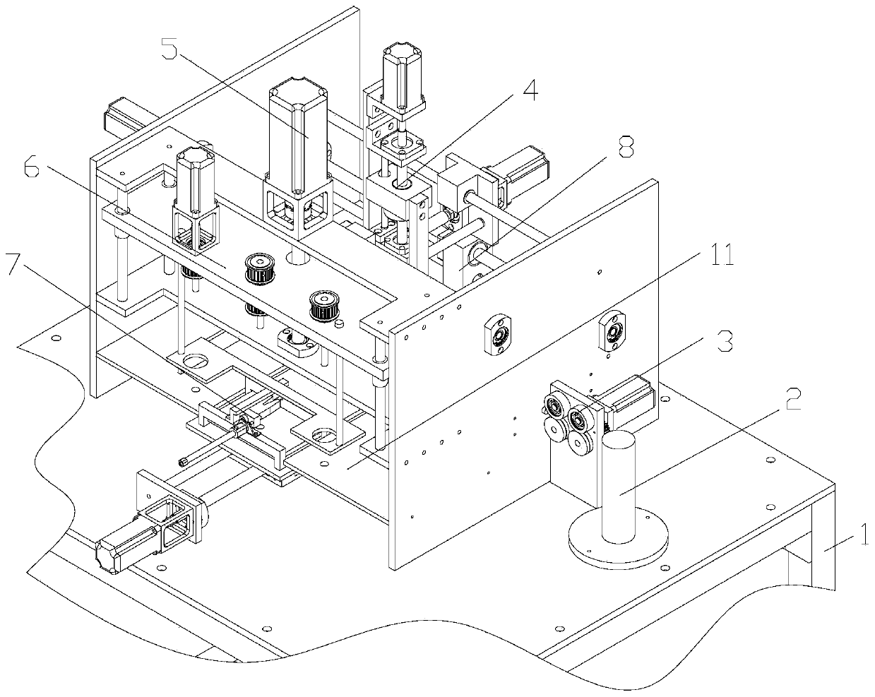
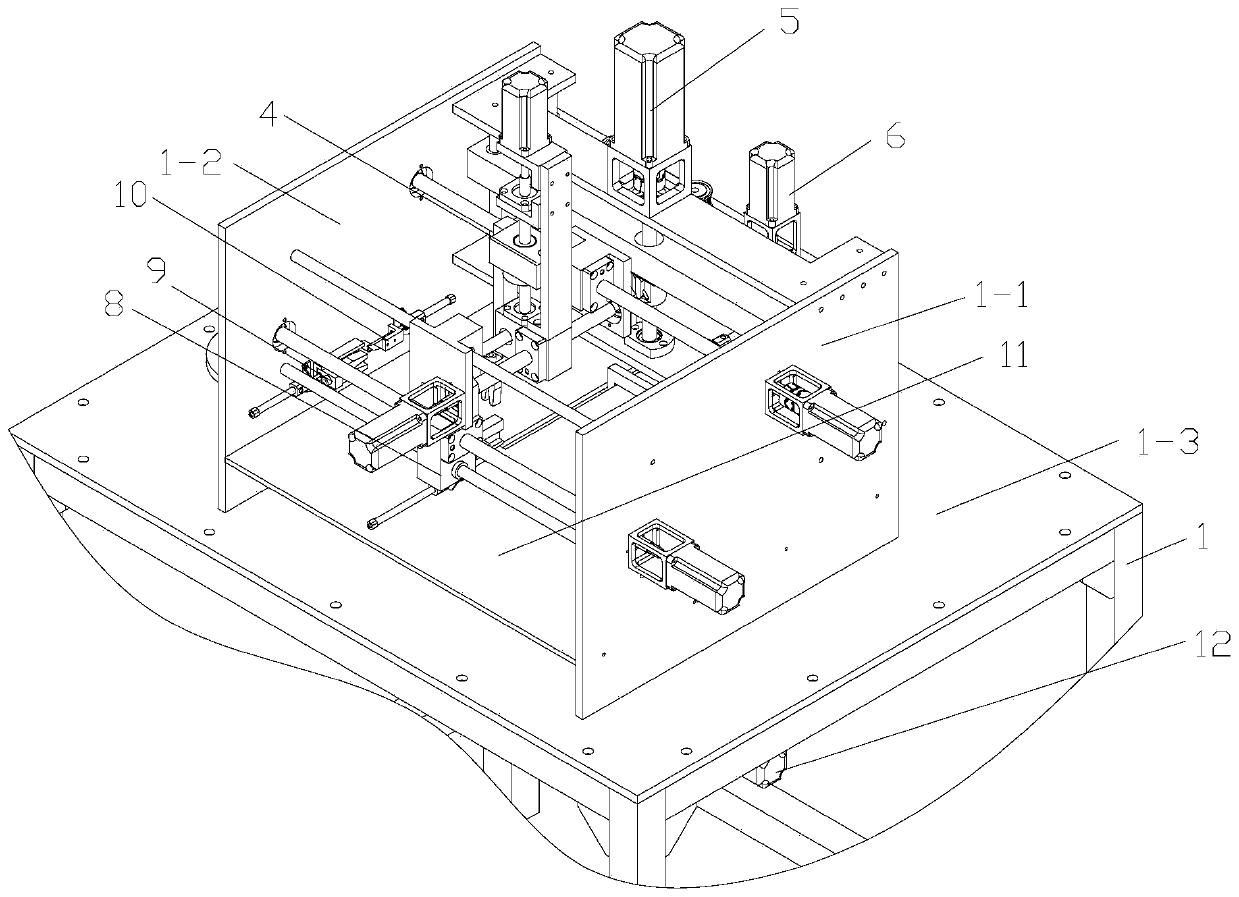
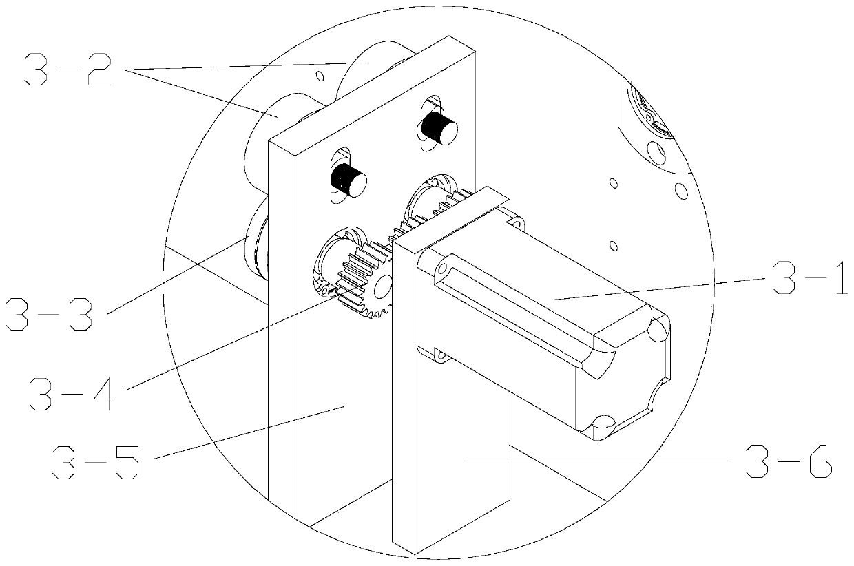
[0059] Such as Figure 1-2 As shown, the present embodiment provides a paper automatic punching and threading knotting machine, including a frame 1, a work surface 1-3 arranged on the frame 1, a left side fixedly arranged above the work surface 1-3 and oppositely arranged. Support 1-1 and right support 1-2, the cardboard 11 that is horizontally installed between the left bracket 1-1 and the right bracket 1-2, the punching mechanism that is arranged on the upper side of the cardboard 11 for punching paper 6 and the threading and knotting components installed on the upper and lower sides of the cardboard 11 for cooperating with the threading and knotting action;

[0060] The front side of the cardboard 11 is provided with a long hole 11-3 that is transparent up and down and extends along the left and right dir...


PUM


Abstract

The invention relates to an automatic paper punching, threading and knotting machine comprising a rack, a work table surface arranged on the rack, left and right brackets fixedly arranged on the worktable surface and oppositely arranged, a paper containing plate horizontally mounted between the left bracket and the right bracket and threading and knotting assemblies mounted on the upper and lowersides of the paper containing plate and used for cooperating to achieve threading and knotting actions. According to the automatic paper punching, threading and knotting machine, an upper clamp mechanism and a lower clamp mechanism cooperate to complete threading work of a binding line, and the upper clamp mechanism cooperates with a front clamp mechanism and the lower clamp mechanism to completeknotting work of the binding line, so that the automation degree is high, the knotting speed is high, and the paper thread stitching efficiency is greatly improved.

Description

technical field [0001] The invention relates to a paper automatic punching, threading and knotting machine. Background technique [0002] The binding of paper such as books or archives, in many cases, uses staples or adopts the traditional thread binding method for automatic binding, but such books are relatively thin. For thicker books, for example, when the number of papers is large (such as 200 or more), because the nails are not long enough to be directly bound with staples or wires, it is necessary to separate and bind multiple layers and then glue them together. For books such as technical manuals, the amount of paper is large, but the printing volume is small. Generally, the perforated binder binding method is used, and the pages are easily lost. However, the current binding methods for punching, threading and knotting of paper are mostly done manually, and the operation is complicated. , time-consuming and labor-intensive, when the workload of paper binding is large...

Claims


Application Information

Patent Timeline
Patent Type & Authority Applications(China)
IPC IPC(8): B42B2/04B42B2/08B42B9/00
Inventor 郑颖陈盈盈朱敏捷徐放应小春郑洪华丁静吴晞东刘建红苏佳宁桑绮温小军曹玉慧
Owner WENZHOU ELECTRIC POWER BUREAU
Learn More