Wind power installation and method of operating it

A technology of wind equipment and operation connection, which can be used in mechanical equipment, wind turbines, wind turbine combinations, etc., and can solve problems such as negative effects

Active Publication Date: 2009-07-15
GAMESA INNOVATION & TECH SA
View PDF4 Cites 12 Cited by
  • Summary
  • Abstract
  • Description
  • Claims
  • Application Information

AI Technical Summary

Problems solved by technology

However, substantial deviations can have a negative effect on

Method used


Image

  • Wind power installation and method of operating it
  • Wind power installation and method of operating it
  • Wind power installation and method of operating it

Examples


Embodiment Construction

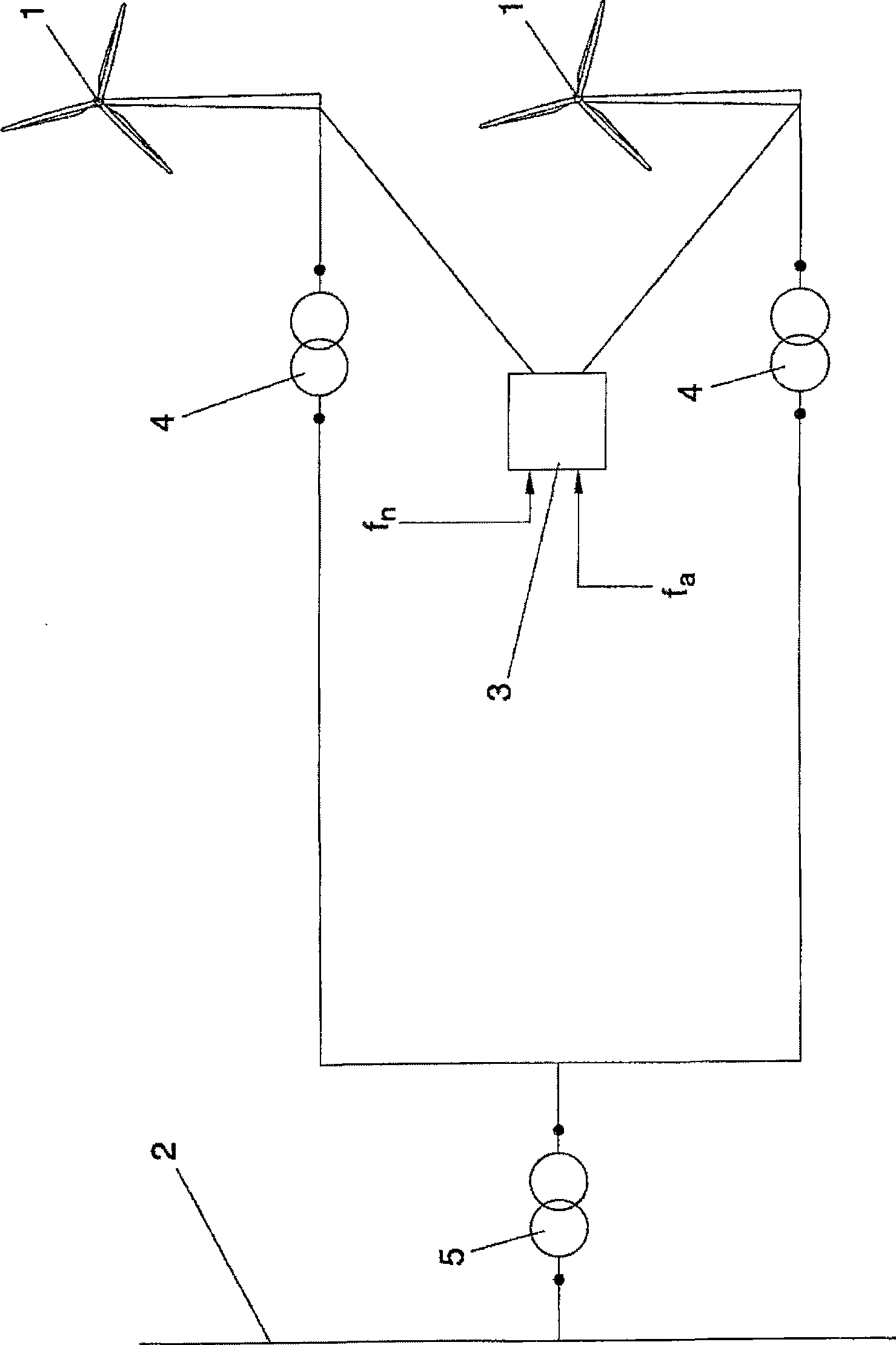
[0059] figure 1 A wind power installation comprising a plurality of wind turbines or wind generators 1 is schematically shown, each wind turbine or wind generator being connected via a first transformer 4 to a second transformer 5 by means of which the wind turbines 1 are connected to An electrical grid or network 2 distributes electrical power to a plurality of consumers (not shown) connected to the network. Traditionally, other power generating systems (not shown) are also connected to the network.

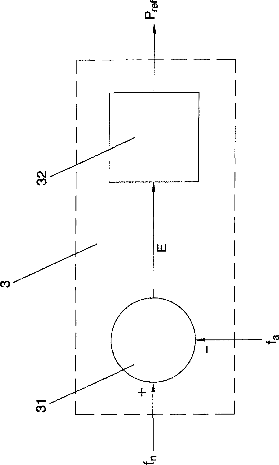
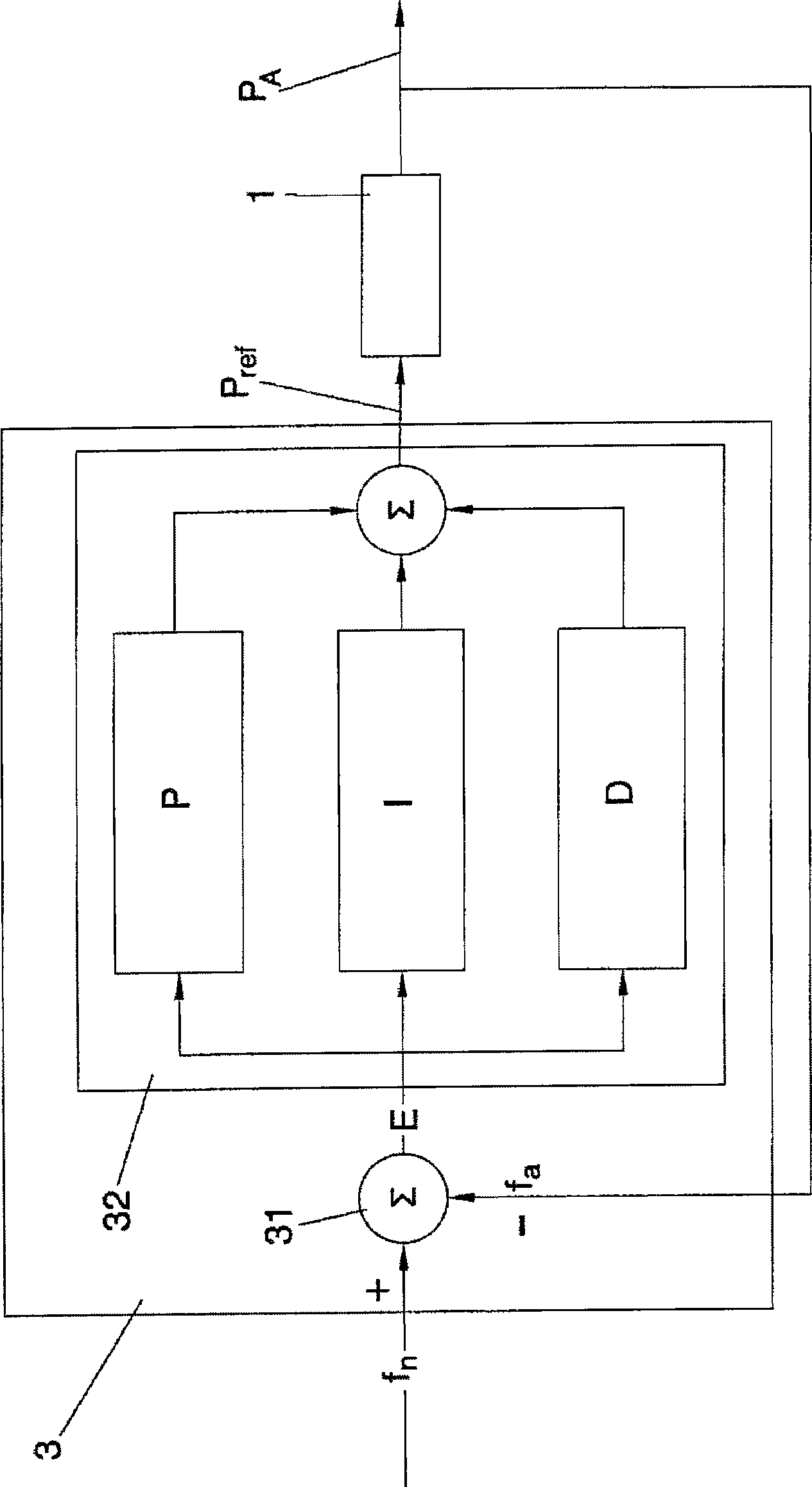
[0060] Furthermore, a control system or controller 3 is provided (one controller may be used for the whole plant, or a separate controller may be provided for each wind turbine 1 or group of wind turbines). The controller 3 receives (e.g. from internal memory or from a remote control station) the nominal frequency (f n ), an indication of the frequency at which the network 2 preferably operates. Typically, this frequency can be 50Hz or 60Hz.

[0061] Likewise, the controlle...


PUM


Abstract

The purpose of the invention is to reduce the contribution of wind power installations to frequency errors on the grid, and preferably to contribute to the elimination of such errors. Thus, the method involves the use of PID control and/or control with hysteresis so as to regulate the active power injected into the grid, in view of the deviation between a measured grid frequency and the nominal grid frequency.

Description

technical field [0001] The present invention relates to the field of wind energy systems and equipment, and in particular to a method for controlling the power generated by such systems and equipment to be supplied to a network or grid for power distribution. Background technique [0002] Wind energy systems and devices include one or more wind generators or turbines arranged to generate electrical energy through wind-induced rotation. Electric energy produced by one or more of these generators (eg by several generators forming part of a so-called "wind farm" or constituting such a "wind farm") is supplied to a grid or network for energy distribution. Usually, a large number of electric generators are connected to the grid, and usually several electricity consumers are also connected to the grid. [0003] In order to keep the voltage and frequency on the network substantially constant, it is important that the power input to the grid at each moment is exactly equal to the p...

Claims


Application Information

Patent Timeline
IPC IPC(8): H02J3/38H02J3/46
CPCF05B2270/337Y02E10/723Y02E10/725F05B2220/706F05B2220/702F03D7/044F05B2270/1033F05B2270/309F05B2270/1041F05B2270/706H02P2009/004Y02E10/763F03D7/0284H02J3/386H02J3/48F05B2220/704F03D9/003F05B2270/70H02P9/42H02P2101/15F03D9/255H02J2300/28H02J3/381Y02E10/72Y02E10/76H02J3/472F03D7/04
Inventor B·安德森
Owner GAMESA INNOVATION & TECH SA
Why Eureka
Try Eureka