Laser marker

A laser marking and laser technology, applied in the field of marking devices, can solve the problems of large consumables, large volume, and large volume of laser marking machines, and achieve the effect of reducing the loss of light

Inactive Publication Date: 2009-07-22
NINGBO WELL LASER TECH
View PDF1 Cites 15 Cited by
  • Summary
  • Abstract
  • Description
  • Claims
  • Application Information

AI Technical Summary

Problems solved by technology

But its disadvantages are that the laser marking machine is bulky and requires corresponding cooling facilities. It is inconvenient to move, has high environmental requirements and is difficult to maintain. It can only process some flat workpieces, and cannot process some three-dimensional and large workpieces. There are great limitations in marking and processing, which greatly reduces its application range
The laser marking machine is bulky, inconvenient to move, has high environmental requirements and is difficult to maintain, and requires a huge cooling device during the marking proces

Method used


Image

  • Laser marker
  • Laser marker
  • Laser marker

Examples


Embodiment Construction

[0020] The present invention will be further described in detail below in conjunction with the accompanying drawings and embodiments.

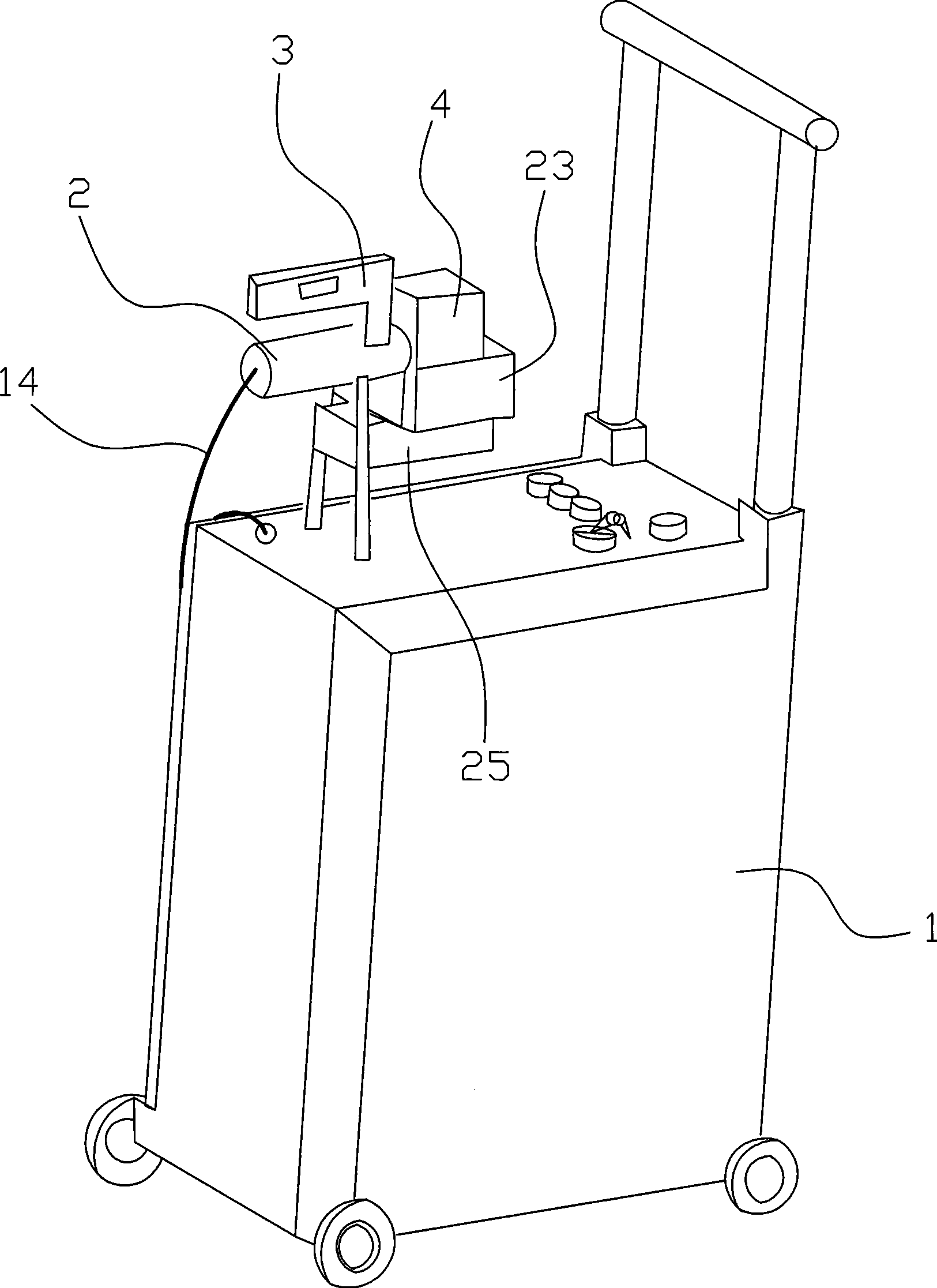
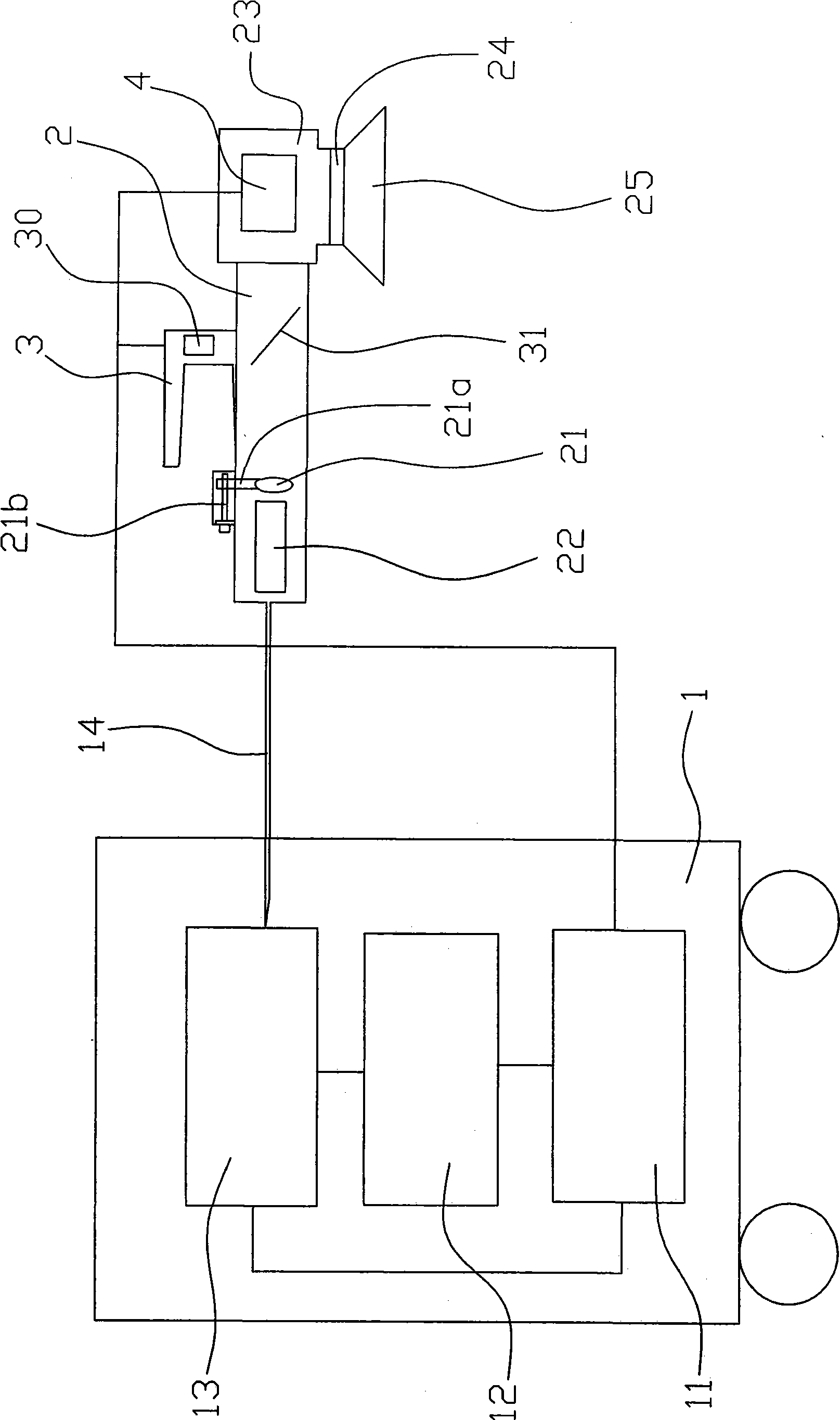
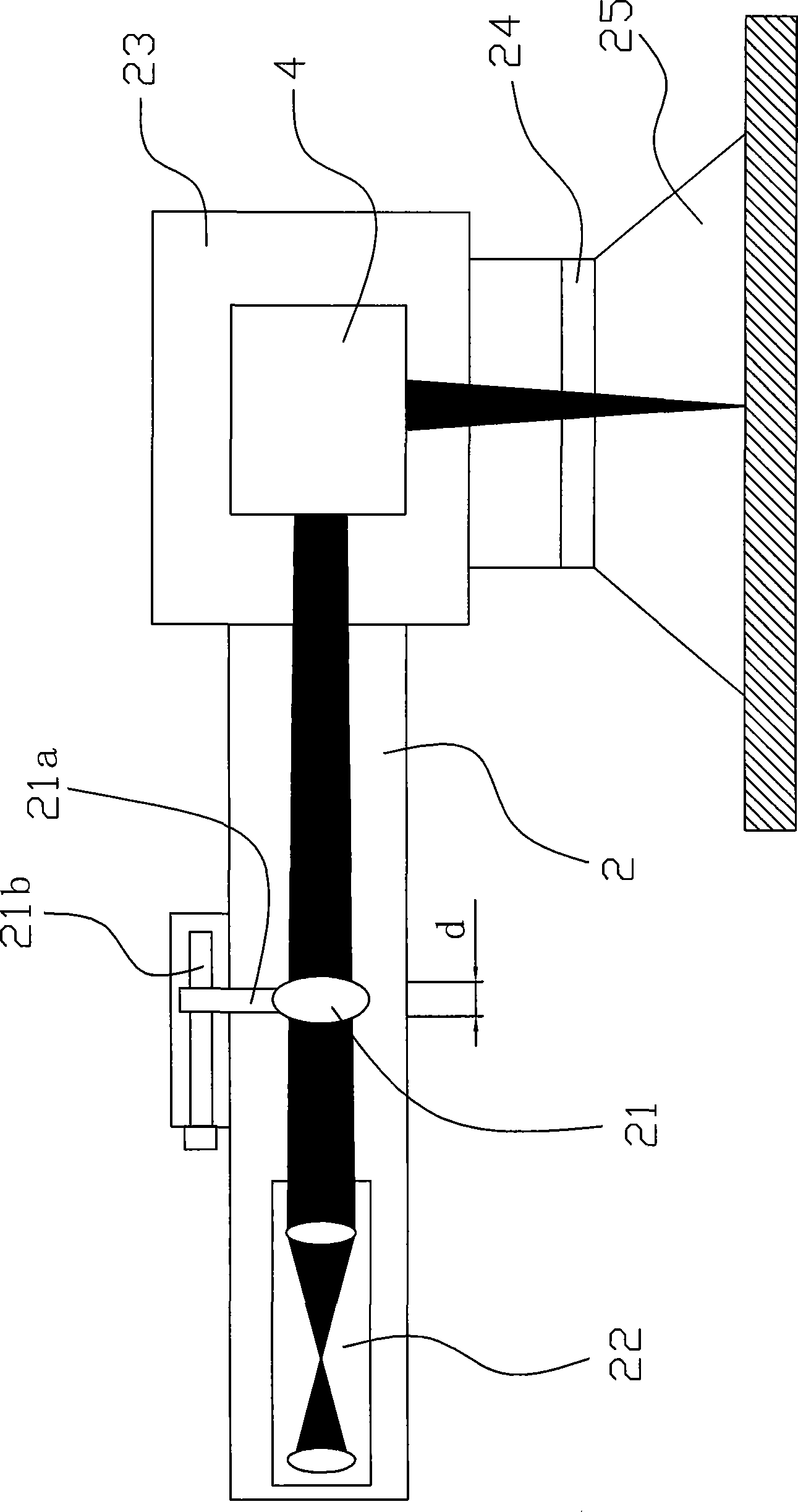
[0021] like figure 1 , figure 2 and image 3 As shown, the laser marker in this embodiment includes a laser 13 , an embedded industrial control system 12 and a galvanometer system 4 . The embedded industrial control system 12 , the laser 13 , and the vibrating mirror system 4 form a circuit through wires and power supply, and the vibrating mirror system 4 is arranged on the marking working head 23 . The industrial control system 12 is connected with the laser 13 and the vibrating mirror system 4, the laser 13 is a fiber laser, and the laser 13 and the embedded industrial control system 12 are placed in a movable mobile box 1, and the laser 13 is connected to the focusing device through an optical fiber 14 are connected, and the focusing device is connected with the galvanometer system 4 through adaptation. The focusing device is composed ...


PUM


Abstract

The invention relates to a laser marking machine, which comprises a laser (13), an embedded industrial control system (12) and a galvanometer system (4), wherein the embedded industrial control system (12) and the laser (13) form a loop with a power supply through conducting wires, and the galvanometer system (4) is arranged on a marking working head (23). The laser marking machine is characterized in that the laser (13) is an optical fiber laser, and the laser (13) and the embedded industrial control system (12) can be positioned in a movable moving box (1); the laser (13) is connected with a focusing device through an optical fiber (14); and the focusing device is adapted together with the galvanometer system (4). Adopting a semiconductor pump fiber laser as a light source, the laser marking machine has the advantages of simple structure, small volume, high conversion efficiency, good laser beam quality, long service life and no maintenance so that a bulky cooling device is not needed in the marking process for the convenience of movable marking. Besides, the movable optical fiber laser marking machine not only requires a simple environment without constant temperature, constant humidity and a water-cooling facility, but also is applicable to a severe environment, thereby having the advantages of least material consumption, international common software, easy learning and understanding, small volume, light weight, small occupied area, and long service life.

Description

technical field [0001] The invention relates to a marker, in particular to a laser marker. Background technique [0002] There is an existing Chinese utility model patent No. 02265752.5 titled "Laser Marking Device with Translating Adjustable Light Guide System", which proposes a structure, which is characterized in that there is a translation between the laser light source and the workpiece to be marked. Adjustable light guide system, the system includes two total reflection mirrors, a focusing scanning system composed of focusing mirrors, X and Y scanning mirrors, and a translation device is installed between the two total reflection mirrors and between the total reflection mirror and the focusing scanning system. tuning device. This can keep the laser light source and the workpiece stationary, and adjust the distance between the two total reflection mirrors and the distance between the total reflection mirror and the focusing scanning system through the translation adjus...

Claims


Application Information

Patent Timeline
IPC IPC(8): B41J2/475B41J3/407H01L21/00
Inventor 谭威俞国麟武松
Owner NINGBO WELL LASER TECH
Why Eureka
Try Eureka