
Material flow control apparatus and method for sintered batching ore storage bin

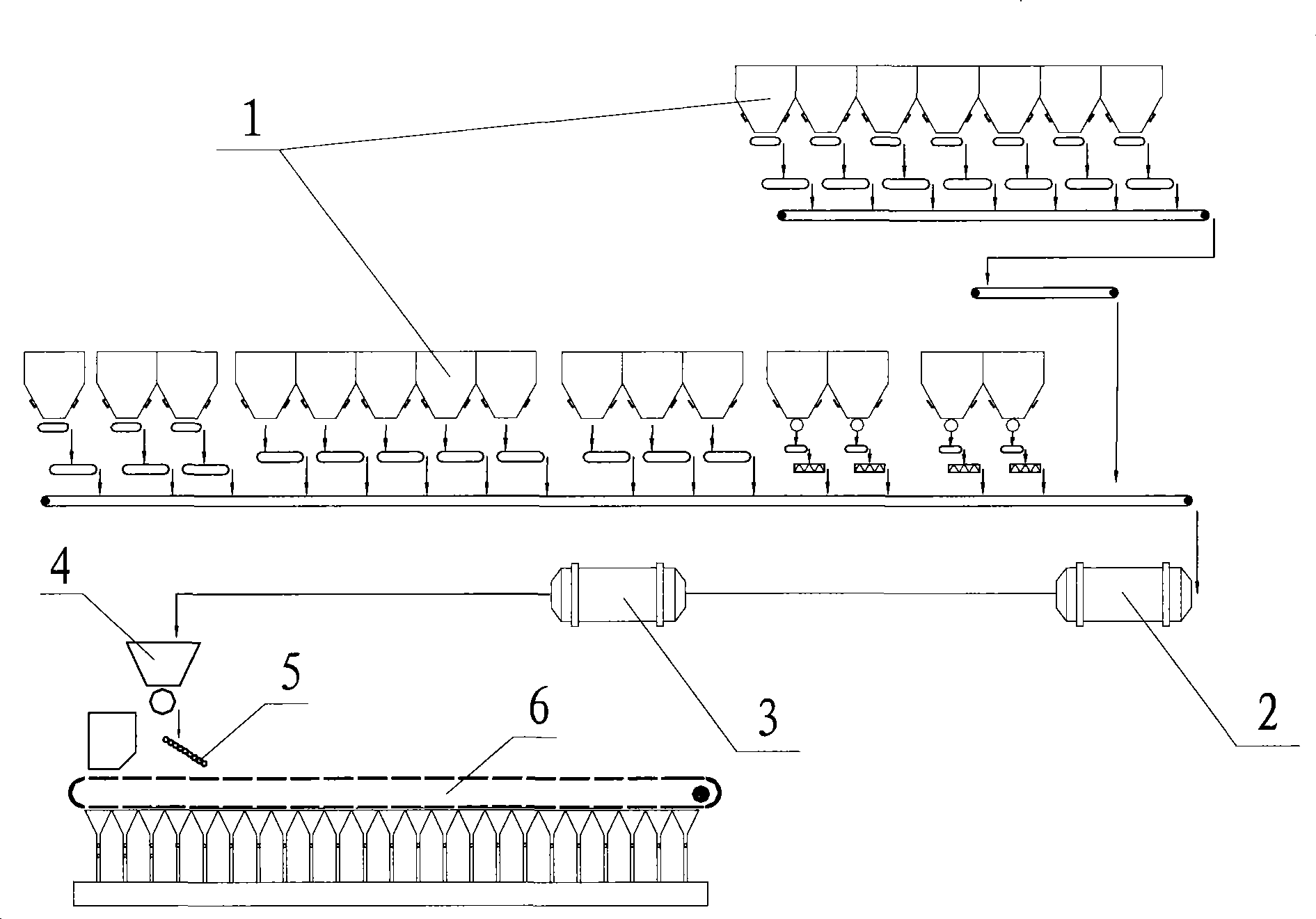
A silo and material flow technology, applied in the field of control, can solve problems such as affecting sintering production and reducing sintering productivity, and achieve the effects of improving sintering productivity and avoiding aggravation of material blockage.

Active Publication Date: 2009-07-22
ZHONGYE-CHANGTIAN INT ENG CO LTD
View PDF0 Cites 25 Cited by
  • Summary
  • Abstract
  • Description
  • Claims
  • Application Information

AI Technical Summary

Problems solved by technology

This will seriously affect the smooth progress of sintering production and reduce sintering productivity

Method used


Image

  • Material flow control apparatus and method for sintered batching ore storage bin
  • Material flow control apparatus and method for sintered batching ore storage bin
  • Material flow control apparatus and method for sintered batching ore storage bin

Examples


Embodiment 2

[0067] The difference between the device in the second embodiment and the first embodiment is that the control device 8 further includes a vibrator 86 arranged on the side wall of the mine bin 7 .

[0068] refer to Figure 6a with Figure 6b , are schematic diagrams of the installation positions of two vibrators and four vibrators, respectively.

[0069] On the frustum-shaped side wall of the bottom of the mine bin 1, 2 or 4 or more vibrators 86 are evenly arranged.

[0070] The vibrator 86 is connected with the blockage judging unit 83 , receives the blockage signal sent by the blockage judging unit 83 , starts to work, and beats the side wall of the mine bin 1 to eliminate the blockage in the mine bin 1 .

[0071] In order to remove the blockage in the mine bin 1 by beating the side wall of the mine bin 1 with the vibrator 86, the side wall at the bottom of the mine bin 1 must be made of steel plate.

[0072] In actual production, the long-time work of the vibrator 86 wil...


PUM


Abstract

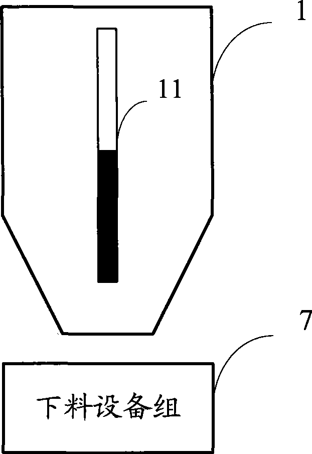
The invention specifically discloses a material flow control device applied to a sintering proportioning ore bunker. The device is connected with a blanking device group and comprises an actual flow acquisition unit, a set flow acquisition unit and a blocking material judgment unit, wherein, the actual flow acquisition unit is connected with a weighing device of the blanking device group to acquire the actual value of blanking flow of the blanking device in real time; the set flow acquisition unit is connected with an electric motor to acquire the set value of blanking flow of the blanking device in real time; the blocking material judgment unit is used for outputting a blocking material warning signal when the ratio of the actual value to the set value of the blanking flow of the blanking device is less than the preset percentage. The invention also discloses a material flow control method applied to the sintering proportioning ore bunker. With the device and method of the invention adopted, the material flow state inside the ore bunker can be detected in real time and the sintering production can run smoothly.

Description

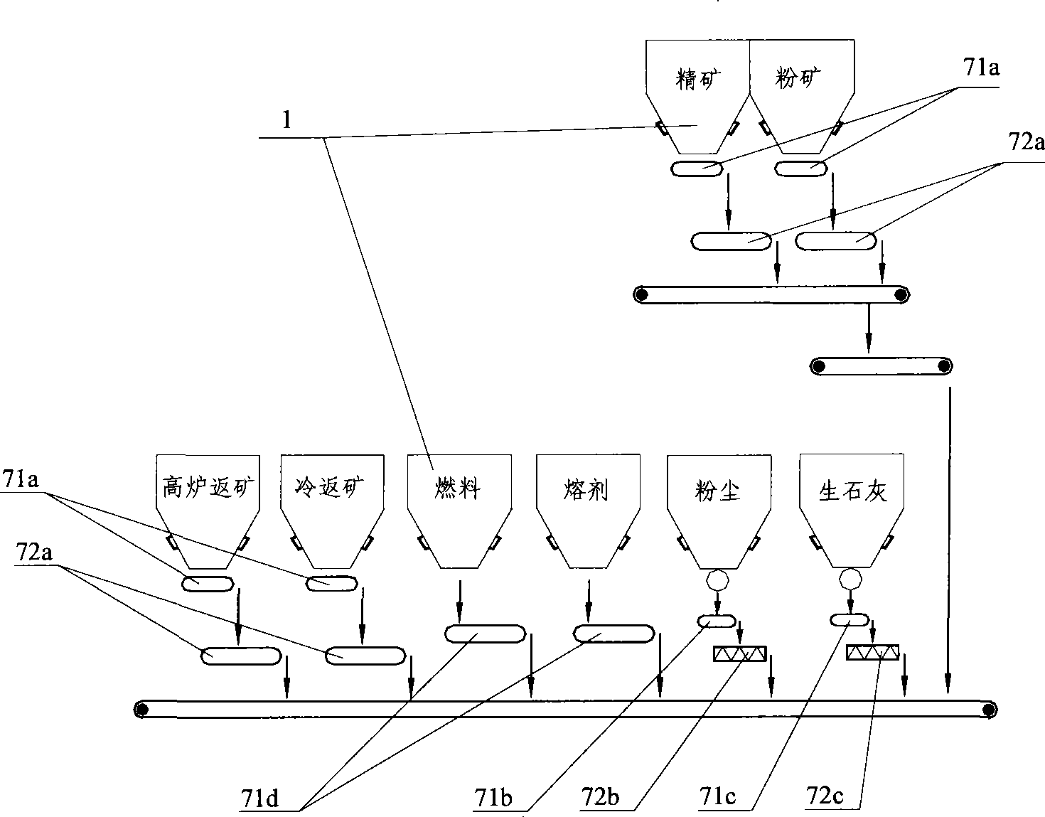
technical field [0001] The invention relates to the field of control, in particular to a material flow control device and method for sintering batching bins. Background technique [0002] refer to figure 1 , is the process flow diagram of the batching system of the sintering plant. [0003] The batching workshop of the sintering plant is equipped with multiple large ore bins 1, which are used to store various materials required for sintering production, such as concentrate, fine ore, blast furnace return, fuel, flux, etc. The batching system calculates the discharge flow rate of each ore bin 1 in proportion according to the comprehensive conveying volume, and sends various materials required for sintering production to the primary mixer 2 through the mixing belt conveyor. After adding water once in the primary mixer 2, the material is sent to the secondary mixer 3 for secondary water addition. After being output from the secondary mixer 3, it falls to the mixing tank 4 th...

Claims


Application Information

Patent Timeline
IPC IPC(8): F27B21/10F27B21/14G05D7/06
Inventor 刘雁飞
Owner ZHONGYE-CHANGTIAN INT ENG CO LTD
Learn More