
Liquid crystal optical grating module, two-dimensional/three-dimensional switchable display and its driving method

A liquid crystal grating and driving method technology, which is applied to static indicators, instruments, electrical components, etc., can solve the problems of complex driving, poor picture fineness, and high cost of liquid crystal grating mold opening, so as to achieve simple driving mode and high fineness of the picture , low-cost effect

Inactive Publication Date: 2009-07-22
TIANMA MICRO ELECTRONICS CO LTD
View PDF0 Cites 35 Cited by
  • Summary
  • Abstract
  • Description
  • Claims
  • Application Information

AI Technical Summary

Problems solved by technology

Some technical solutions realize the switching of 2D / 3D display by adding a controllable liquid crystal grating to the display, or add a guest-host liquid crystal grating to realize the switching of 2D / 3D display, but only when the direction of the line connecting the eyes is perpendicular to the direction of the barrier Stereoscopic images can only be observed, and there are also technical solutions that use box-type parallax barriers and stereoscopic image display devices to display 3D images rotated in the horizontal direction / vertical direction, but there are also the following problems: using two segmented terminals and two The combination of two common terminals controls the liquid crystal display, and the drive is more complicated; when switching the display state of the horizontal / vertical direction, the display state of the fence needs to be changed, and 3D images cannot be displayed in the horizontal / vertical direction at the same time; there is a small gap of about 10um between pixels, The mold opening cost of liquid crystal grating is relatively high; and the above-mentioned gratings all use strip gratings to realize 3D display, and the synthesis method of stereoscopic image pairs is to extract pixels every other column, so that the fineness of the picture is poor

Method used


Image

  • Liquid crystal optical grating module, two-dimensional/three-dimensional switchable display and its driving method
  • Liquid crystal optical grating module, two-dimensional/three-dimensional switchable display and its driving method
  • Liquid crystal optical grating module, two-dimensional/three-dimensional switchable display and its driving method

Examples


Embodiment Construction

[0032] In order to make the object, technical solution and advantages of the present invention clearer, the present invention will be further described in detail below in conjunction with the accompanying drawings and embodiments. It should be understood that the specific embodiments described here are only used to explain the present invention, not to limit the present invention.

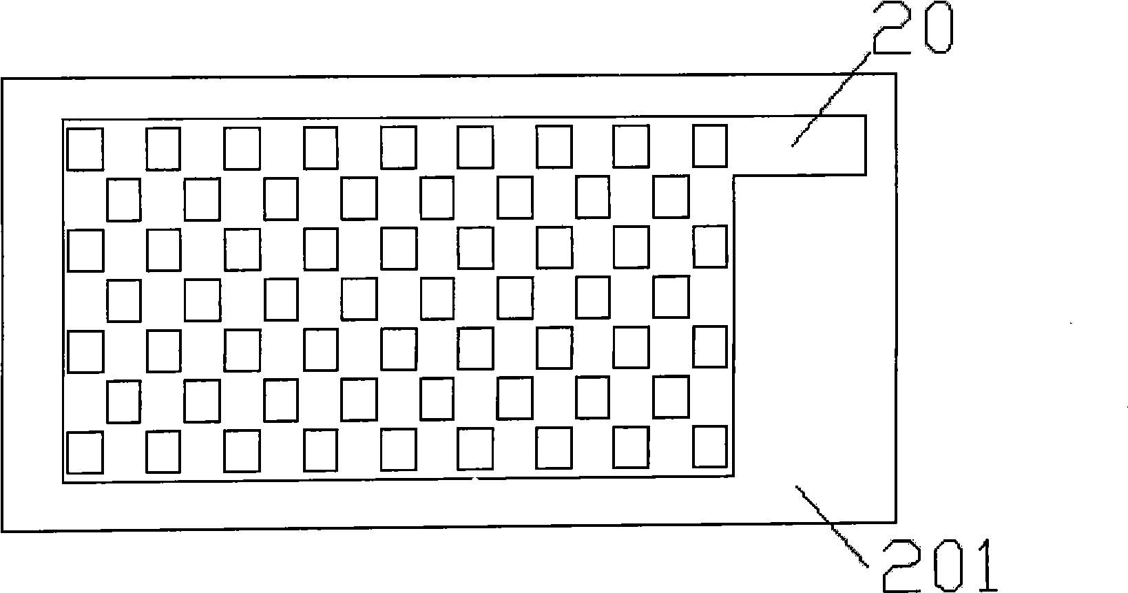
[0033] In the embodiment of the present invention, the electrodes on the substrate of the liquid crystal grating module are designed to be distributed in a checkerboard shape, and the electrode areas and non-electrode areas are arranged in a staggered manner both horizontally and vertically.

[0034] image 3 and Figure 4 The design shapes of the electrodes on the two substrates of the liquid crystal grating module provided by the embodiment of the present invention are shown, image 3 The blank part in the middle represents the electrode region, and the rest represents the non-electrode region....


PUM


Abstract

The invention is applicable to the field of display apparatus and provides a liquid crystal raster module, a two-dimensional / three-dimensional switchover type display apparatus and a driving method thereof; wherein, the liquid crystal raster module comprises two substrates, the electrodes on one of the two substrates are in chessboard type distribution, and the electrode areas and non-electrode areas are all alternatively arrayed in the horizontal direction and vertical direction. In the invention, 3D effect can be observed both from the horizontal direction and vertical direction when the raster is at work, the raster display state switchover is unnecessary, a combination of a segment terminal and a common terminal can be adopted, namely, the electrode lead control display apparatuses on the two substrates of the liquid crystal raster module, the driving mode is simpler, furthermore, the liquid crystal raster pixel size and the pixel interval are larger and the production process is mature, therefore, the cost is low, meanwhile the 3D image synthesis mode of the invention adopts interval dot pixel extraction, thus the subtleness of the image is high.

Description

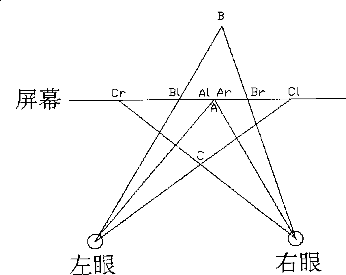
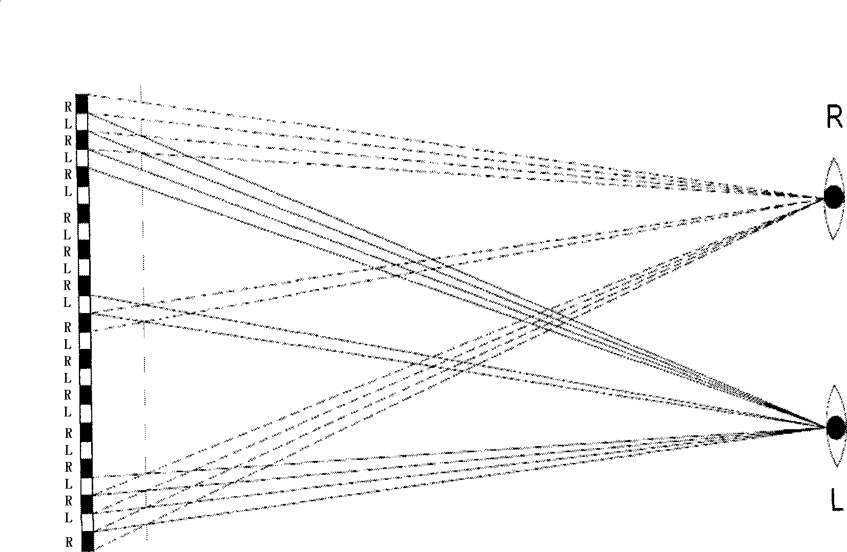
technical field [0001] The invention belongs to the field of displays, and in particular relates to a liquid crystal grating module, a two-dimensional / three-dimensional switchable display and a driving method thereof. Background technique [0002] Now the three-dimensional (3D) display function of the display is gradually becoming an important factor to attract consumers, and has been applied in many products, such as mobile communication terminals, televisions, computers, vehicle display screens, etc., 3D applications will surely follow The maturity of technology has penetrated deeper into our lives. [0003] The current 3D solutions use strip gratings to selectively block pixels, and use optical principles to cause visual differences in the human eye. Finally, people can see a 3D image within a certain viewing angle range of the display screen. figure 1 For the basic binocular parallax principle diagram, figure 2 The principle of realizing 3D display by using the parall...

Claims


Application Information

Patent Timeline
Patent Type & Authority Applications(China)
IPC IPC(8): G02F1/133G09G3/36H04N13/00
Inventor 谢佳牛磊孙杨
Owner TIANMA MICRO ELECTRONICS CO LTD
Learn More