Tripod constant velocity universal joint

A constant velocity universal joint and tripod-type technology, which is applied in elastic couplings, mechanical equipment, couplings, etc., can solve problems such as increased costs, and achieve the effects of increased life and reduced surface pressure

Inactive Publication Date: 2009-07-22
NTN CORP
View PDF0 Cites 5 Cited by
  • Summary
  • Abstract
  • Description
  • Claims
  • Application Information

AI Technical Summary

Problems solved by technology

[0010] However, in position control using a locator and a retaining ring, in addition to the cost of these parts, forming a groove for the retaining ring on the shaft requires processing costs, resulting in an increase in cost.

Method used


Image

  • Tripod constant velocity universal joint
  • Tripod constant velocity universal joint
  • Tripod constant velocity universal joint

Examples


Embodiment Construction

[0048] Below, according to Figure 1 to Figure 10 Embodiments of the present invention will be described.

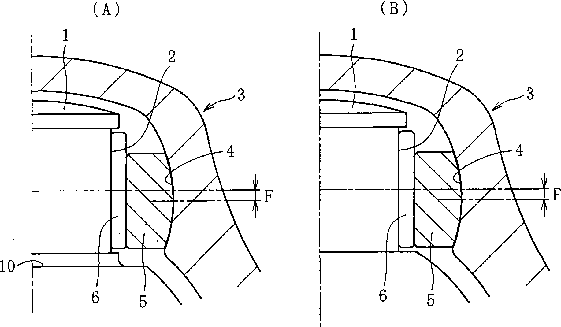
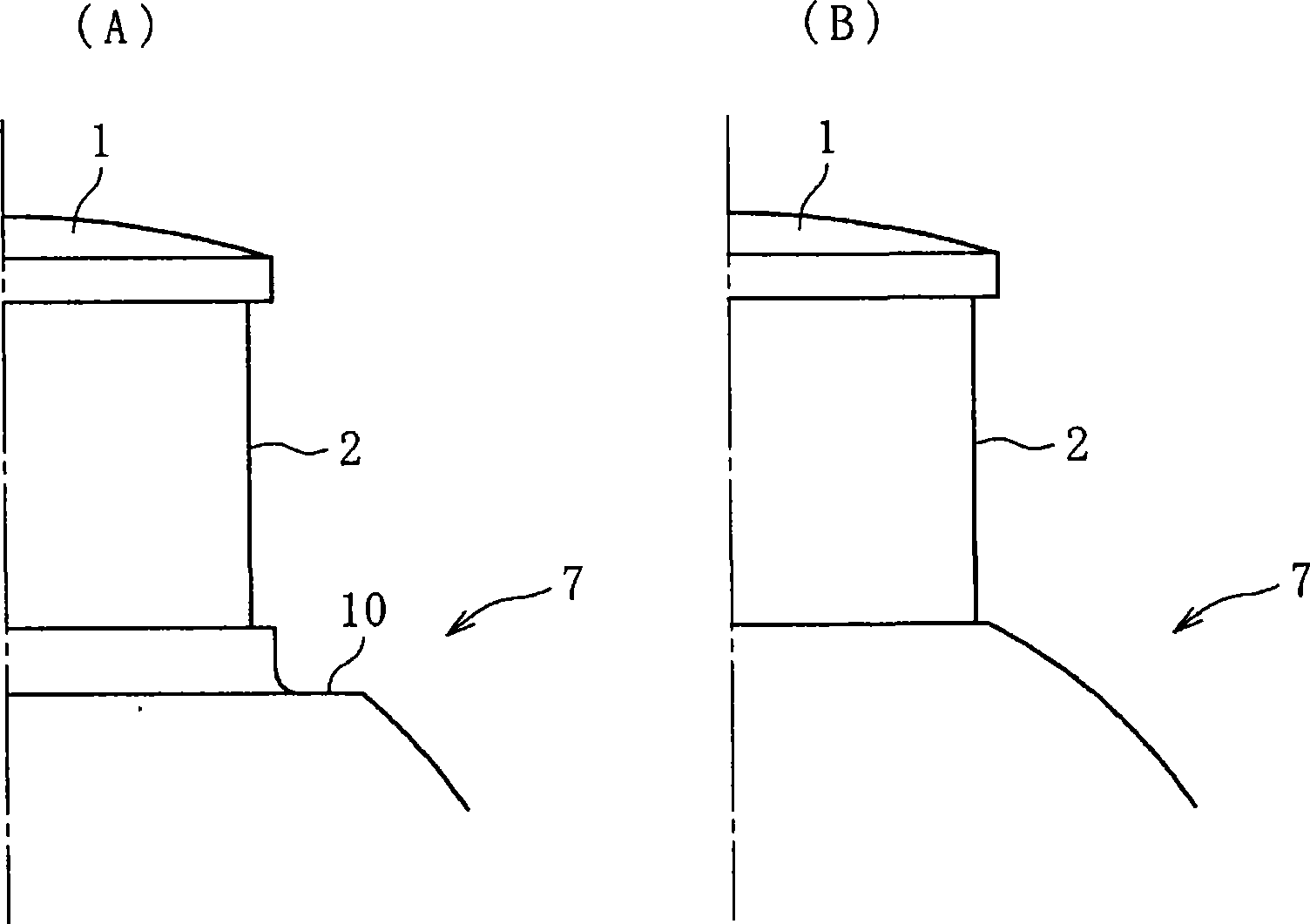
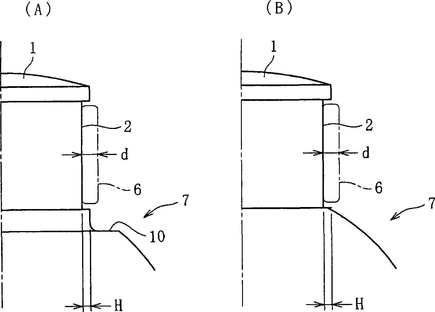
[0049] The basic form of the constant velocity universal joint of the present invention and Figure 11A The same as the conventional tripod type constant velocity universal joint. The parts that are different from the conventional ones are the shape of the peripheral surface of the pin shaft and the shape of the inner diameter of the opening of the outer joint member. Thus, parts different from conventional ones will be described based on the following drawings.

[0050] Such as figure 1 As shown in (A) and (B), in the first embodiment of the present invention, grooves 2 are formed on the outer peripheral surface of the foot shaft 1 in the circumferential direction. figure 1 The difference between (A) and (B) is the presence or absence of the root edge side step portion 10 of the foot shaft 1 . The groove portion 2 accommodates a plurality of needle rollers 6 , and...


PUM


Abstract

The invention relates to a tripod constant velocity universal joint in which only journal surfaces of leg shafts can restrain the position of needle rollers relative to the axial direction. In the tripod constant velocity universal joint, a groove (2) capable of receiving the needle rollers (6) and functioning as a rolling surface for the needle rollers (6) is formed on the outer peripheral surface of a leg shaft (1) in the circumferential direction of the leg shaft. A semisolid or solid lubricant having the consistency number 0, 1, or 2 assists the needle rollers (6) to be retained and aligned in the groove (2).

Description

technical field [0001] The invention relates to a tripod type constant velocity universal joint. Background technique [0002] Usually, constant velocity universal joints (three-leg type constant velocity universal joints), such as Figure 11A with Figure 11B As shown, an outer joint member 51, a tripod member 52 as an inner joint member, and a roller 53 as a torque transmission member are main components (see Patent Document 1). [0003] The outer joint member 51 is composed of an integrally formed mouth portion 54 and a stem portion 55 . The mouth portion 54 is in the shape of a cup with one end open, and track grooves 56 extending in the axial direction are formed at three equal parts in the circumferential direction of the inner periphery. The mouth 54 is viewed from the cross section ( Figure 11B ), it is a non-cylindrical shape in which large diameter portions 54a and small diameter portions 54b alternately appear. That is, the nozzle 54 forms the three track gro...

Claims


Application Information

Patent Timeline
Patent Type & Authority Applications(China)
IPC IPC(8): F16D3/205
CPCF16D3/2055F16D2003/2023
Inventor 福村善一黑田正幸藏久昭友上真杉山达朗
Owner NTN CORP
Why Eureka
Try Eureka