Pump device and vehicle

A pump device and pump part technology, which is applied to the pump device, the components of the pumping device for elastic fluid, the pump, etc., can solve the problems of poor wear resistance of the pump device and the like

Pending Publication Date: 2022-03-04
ANHUI WELLING AUTO PARTS CO LTD +1
View PDF0 Cites 0 Cited by
  • Summary
  • Abstract
  • Description
  • Claims
  • Application Information

AI Technical Summary

Problems solved by technology

However, during the high-speed rotation of the pump part, the pump part will be in contact with other structures of the pump device and wear away. Although there is a lubricating medium on the contact surface between the pump part and

Method used


Image

  • Pump device and vehicle
  • Pump device and vehicle
  • Pump device and vehicle

Examples


Embodiment 1

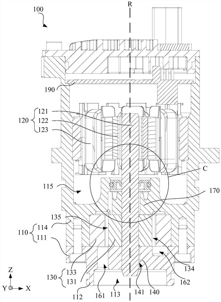
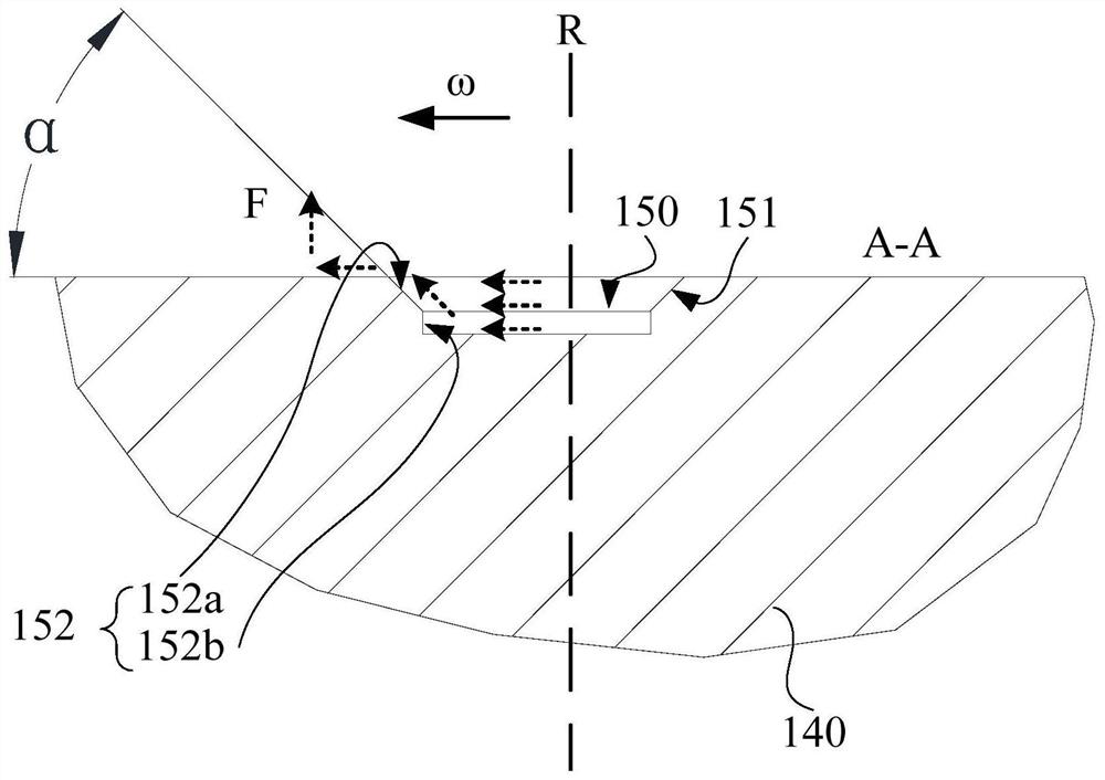
[0106] According to a first aspect of the present invention, a pump device 100 is provided, such as figure 1 and figure 2 As shown, it includes a housing 110 , a motor portion 120 , a pump portion 130 , a first bearing 140 and a thrust lubrication groove 150 . Wherein, the housing 110 has a cavity 115 . The motor part 120 is disposed in the cavity 115 , and the motor part 120 includes a rotating shaft 121 rotating around a central axis of the motor part 120 . The pump part 130 is disposed on one axial side of the motor part 120 and is in contact with the rotating shaft 121 , and the pump part 130 can be driven by the rotating shaft 121 to rotate. The first bearing 140 is connected with the casing 110 and sleeved on the rotating shaft 121 . The first bearing 140 is located on a side of the pump part 130 away from the motor part 120 . The thrust lubricating groove 150 is disposed on the end surface of the first bearing 140 close to the pump part 130 and communicates with the...

Embodiment 2

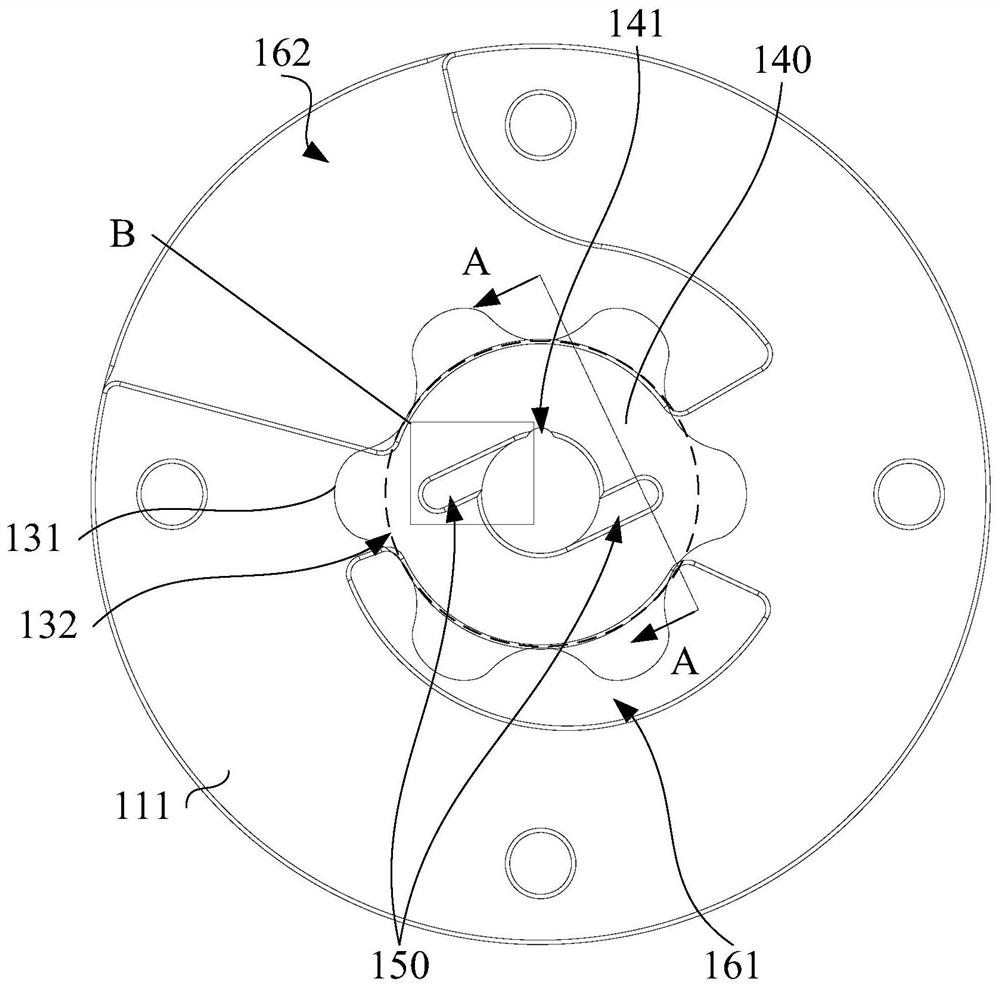
[0138] On the basis of Example 1, as figure 2 As shown, this embodiment explains the specific structure of the pump part 130. Further, the pump part 130 includes a first gear 131, the first gear 131 cooperates with the rotating shaft 121, and a plurality of dedendums of the first gear 131 form teeth The root circle 132 and the dedendum circle 132 extend axially to form an inner circular surface, and the thrust lubricating groove 150 is located in the inner circular surface.

[0139] In this embodiment, the pump part 130 includes a first gear 131 , the first gear 131 is in interference fit with the rotating shaft 121 , and the rotating shaft 121 rotates to drive the first gear 131 to rotate. A plurality of dedendums of the first gear 131 form a dedendum circle 132 . It should be noted that the dedendum circle 132 refers to a circle formed by the root of the tooth groove of the gear. The dedendum circle 132 extends axially to form an inner circular surface, and the thrust lub...

Embodiment 3

[0144] On the basis of the foregoing embodiments, the specific structure of the casing 110 is described in this embodiment. Further, the casing 110 includes a pump cover 111, and the pump cover 111 is arranged on the side of the pump part 130 away from the motor part 120. The pump The cover 111 is connected to the first bearing 140 .

[0145] In this embodiment, the casing 110 includes a pump cover 111 , the pump cover 111 is disposed on the side of the pump part 130 away from the motor part 120 , and the pump cover 111 is connected with the first bearing 140 . The first bearing 140 and the pump cover 111 can be detachably connected, of course, the first bearing 140 and the pump cover 111 can also be fixedly connected. Specifically, the first bearing 140 is integrated with the pump cover 111 , because the integrated structure has better mechanical properties, thereby improving the connection strength between the first bearing 140 and the pump cover 111 . In addition, the firs...


PUM

PropertyMeasurementUnit
Thicknessaaaaaaaaaa

Abstract

The invention provides a pump device and a vehicle. The pump device comprises a shell, a motor part, a pump part, a first bearing and a thrust lubrication groove. Wherein the shell is provided with a cavity; the motor part is arranged in the cavity and comprises a rotating shaft rotating around the central axis of the motor part. The pump part is arranged on the axial side of the motor part and makes contact with the rotating shaft, and the pump part can be driven by the rotating shaft to rotate. The first bearing is connected with the shell, sleeves the rotating shaft and is located on the side, away from the motor part, of the pump part. The thrust lubrication groove is formed in the end face, close to the pump part, of the first bearing and communicates with a shaft hole of the first bearing. Lubricating oil in the thrust lubricating groove can flow to the end face gap between the first bearing and the pump part, so that fluid lubrication is formed on the contact end faces of the first bearing and the pump part, the abrasion condition of the contact end faces of the pump part and the first bearing is greatly improved, power consumption is reduced, and in addition, operation noise of the pump device can be reduced.

Description

technical field [0001] The present invention relates to the technical field of pump devices, in particular to a pump device and a vehicle. Background technique [0002] At present, the pump device includes a motor part and a pump part, and the rotating shaft in the motor part drives the pump part to rotate, thereby realizing liquid compression. However, during the high-speed rotation of the pump part, the pump part will be in contact with other structures of the pump device and wear away. Although there is a lubricating medium on the contact surface between the pump part and other structures, because the end face of the pump part is in plane contact, the plane The contact can only achieve boundary lubrication, and in the state of boundary lubrication, the anti-wear performance of the pump device is poor. Contents of the invention [0003] The present invention aims to solve at least one of the technical problems existing in the prior art or related art. [0004] To this ...

Claims


Application Information

Patent Timeline
IPC IPC(8): F01P5/10F01P11/00F04D13/06F04D29/046F04D29/06F04D29/42F04D29/62
CPCF01P5/10F01P11/00F04D13/06F04D29/426F04D29/628F04D29/061F04D29/046
Inventor 曹小军化豪爽付威葛笑江波
Owner ANHUI WELLING AUTO PARTS CO LTD
Why Eureka
Try Eureka