
Electric Valve

A technology of electric valve and valve needle, which is applied in the direction of lifting valve, valve details, valve device, etc. It can solve the problems of unreliable fixing of coil and valve body, loose stop parts, difficult assembly, etc., and achieve compact structure and high arm strength. Elastic, fixed and reliable effect

Active Publication Date: 2011-06-01
ZHEJIANG SANHUA INTELLIGENT CONTROLS CO LTD
View PDF1 Cites 2 Cited by
  • Summary
  • Abstract
  • Description
  • Claims
  • Application Information

AI Technical Summary

Problems solved by technology

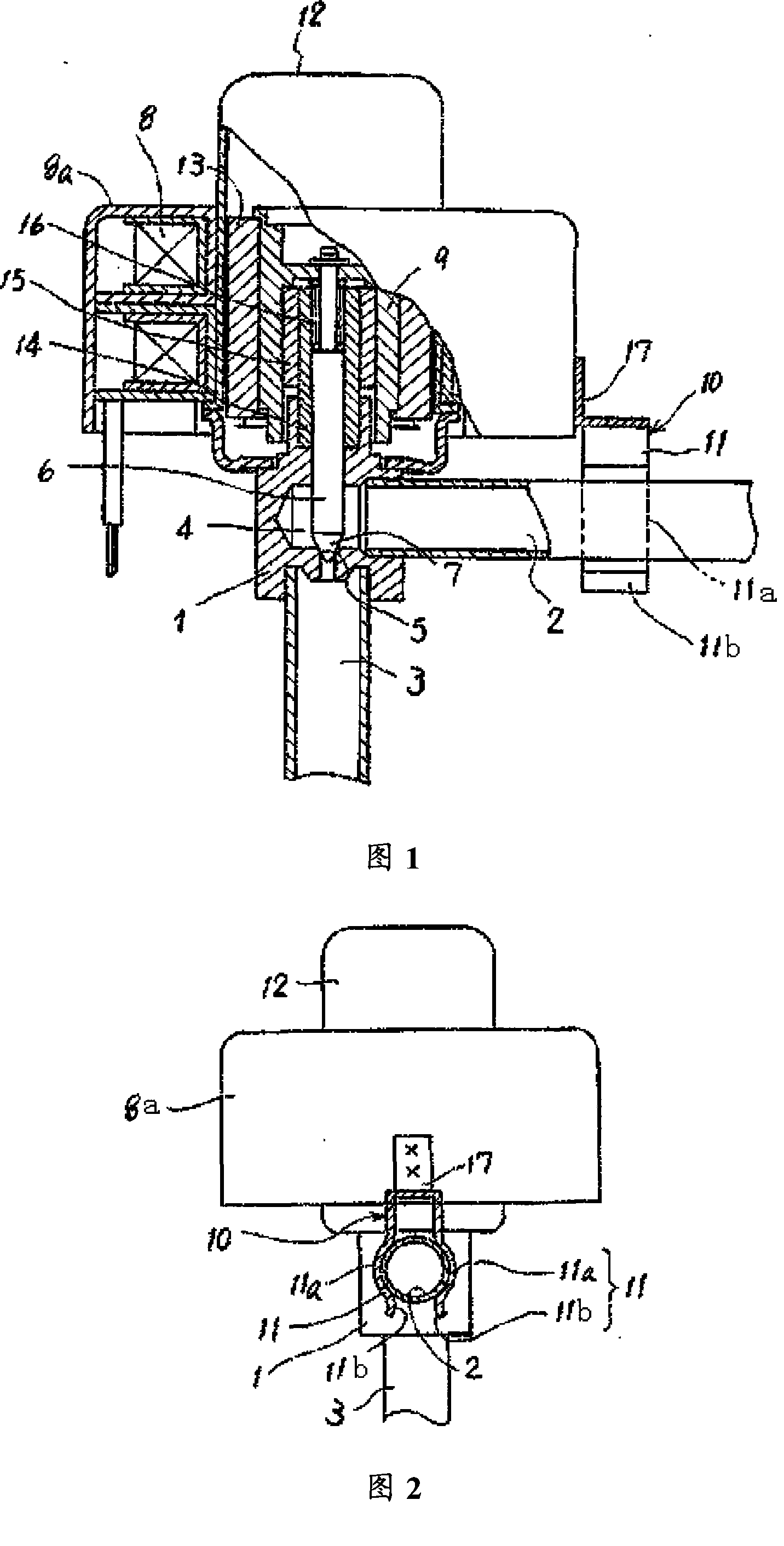
But, because the elastic force generated by the elastic deformation of the lower outer curved section 11 is used to engage the horizontal fluid inlet and outlet pipes, the stoppers fixed on the fluid inlet and outlet pipes will loosen when the elastic force is insufficient. The problem that the relative position between the coil and the valve body is fixed unreliably
[0006] In addition, during the assembly process of the electric valve, the stopper part is fixed on the coil box by spot welding, which must be welded. The above solution also has the disadvantages of poor operability and difficult assembly

Method used


Image

  • Electric Valve
  • Electric Valve
  • Electric Valve

Examples


Embodiment Construction

[0043] The present embodiment will be described in detail below in conjunction with the accompanying drawings.

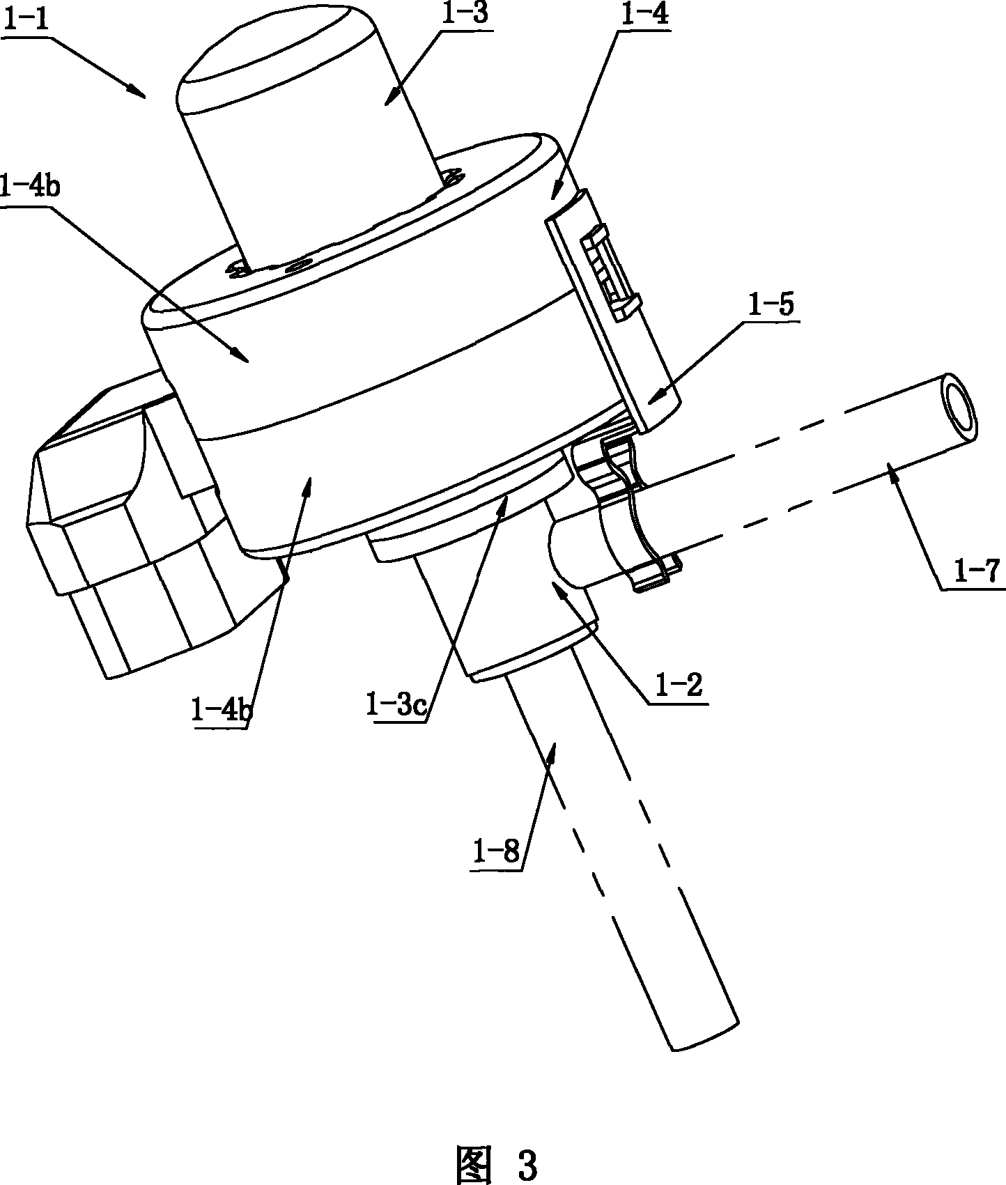
[0044] Referring to Fig. 3, this figure is a three-dimensional structure diagram of the electric valve 1-1 of the present invention.

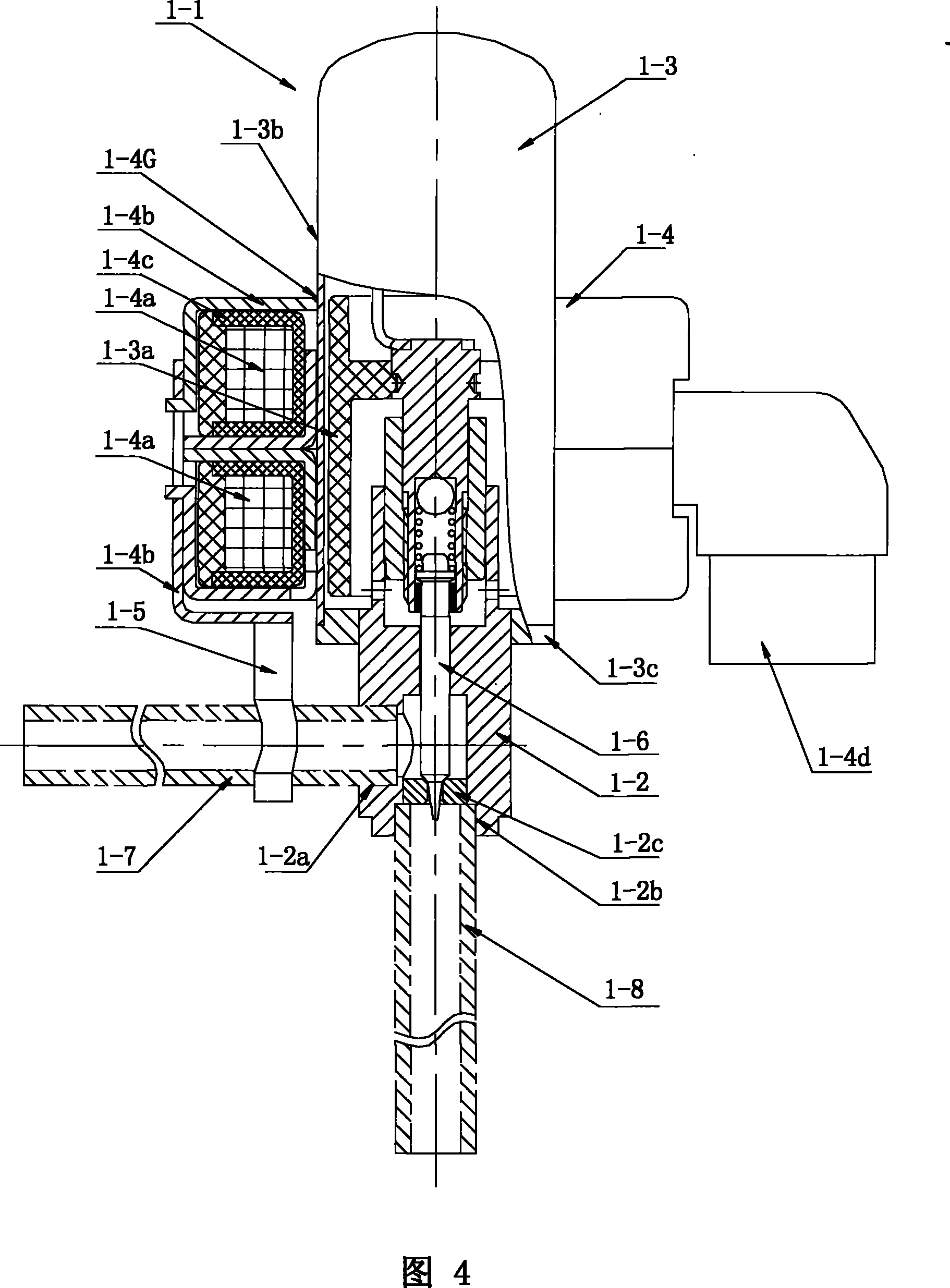
[0045] As shown in the figure, the electric valve 1-1 of the present invention consists of a valve seat 1-2, a rotor 1-3, a stator 1-4 sleeved on the outside of the rotor 1-3, a stopper 1-5 and a valve needle 1. -6 composition; the stepper motor composed of rotor 1-3 and stator 1-4 is set on the valve seat 1-2, and is used to drive the valve needle 1, valve needle 1-6 to move up and down to realize the valve needle 1-6 and valve seat 1 -2 to join or disengage. Arranged in the control system, the horizontal fluid inlet and outlet 1-2a and the vertical fluid inlet and outlet 1-2b of the valve seat 1-2 communicate with the horizontal fluid inlet and outlet pipe 1-7 and the vertical fluid inlet and outlet pipe 1-8 respectively. In orde...


PUM


Abstract

The invention discloses an electric valve, aiming at the problems that the elasticity of a stopping part for preventing a coil from being loosened corresponding to a valve body is low in the prior art; the technical scheme of the invention comprises a valve seat, a valve needle, the stopping part and a stepping motor which is composed of a rotor and a stator for driving the valve needle and the valve seat to joint or detach; the stopping part is fixedly connected with a stator coil box, and internally concave bending parts which are opposite are additionally arranged above externally convex bending parts on two arm parts extended downwards thereof respectively, a clamping part is fixedly arranged on the outside surface of the stator coil box, a clamping opening adaptated with the clamping part is arranged on a basal part of the stopping part and is buttoned with the clamping part on the coil box to realize a clamping connection. The electric valve has the advantages of low working noise, compact structure and good assembling operability; moreover, the vibration reduction is greatly improved for obtaining accurate flow control; therefore, the electric valve is particularly suitable for refrigerators, air conditioning refrigerating units, water heaters and dehumidifiers, thus realizing defrosting, the flow control and on-off control and the like of a heating system.

Description

technical field [0001] The invention relates to a valve, in particular to an electric valve. Background technique [0002] At present, the electric valve used in the refrigeration system is driven by a stepper motor, and the opening of the valve is adjustable to control the flow of the medium in the pipeline. [0003] The solenoid valve with conventional structure includes a cover, an electromagnetic coil set outside the cover, a valve seat connected to the lower part of the cover, and a magnetic rotor, valve needle and valve seat located in the cover; the cover is made of non-magnetic materials such as stainless steel It has a cylindrical structure and is welded to the valve seat; the stator is composed of a yoke iron made of soft magnetic material and a stator coil wound through a coil barrel in the yoke iron. The stator and the rotor form a stepping motor for driving the valve needle Engagement or disengagement with respect to the valve seat. When the system is working,...

Claims


Application Information

Patent Timeline
Patent Type & Authority Patents(China)
IPC IPC(8): F16K31/04F16K1/38
CPCF25B41/062F16K27/0254F16K31/04F25B2500/12Y02B30/70F25B41/35
Inventor 詹才意蒋炜炜陈伯汀
Owner ZHEJIANG SANHUA INTELLIGENT CONTROLS CO LTD
Learn More