Memory device, controller and switching method for flash memory

A memory controller and storage device technology, applied in static memory, read-only memory, information storage, etc., can solve problems such as inconvenience, and achieve the effect of meeting storage requirements

Active Publication Date: 2009-07-29
EMTOPS ELECTRONICS CORP
View PDF0 Cites 21 Cited by
  • Summary
  • Abstract
  • Description
  • Claims
  • Application Information

AI Technical Summary

Problems solved by technology

However, having to carry and use multiple flash drives of different types of flash memory is quite inconvenient for the needs of such users

Method used


Image

  • Memory device, controller and switching method for flash memory
  • Memory device, controller and switching method for flash memory
  • Memory device, controller and switching method for flash memory

Examples


no. 1 example

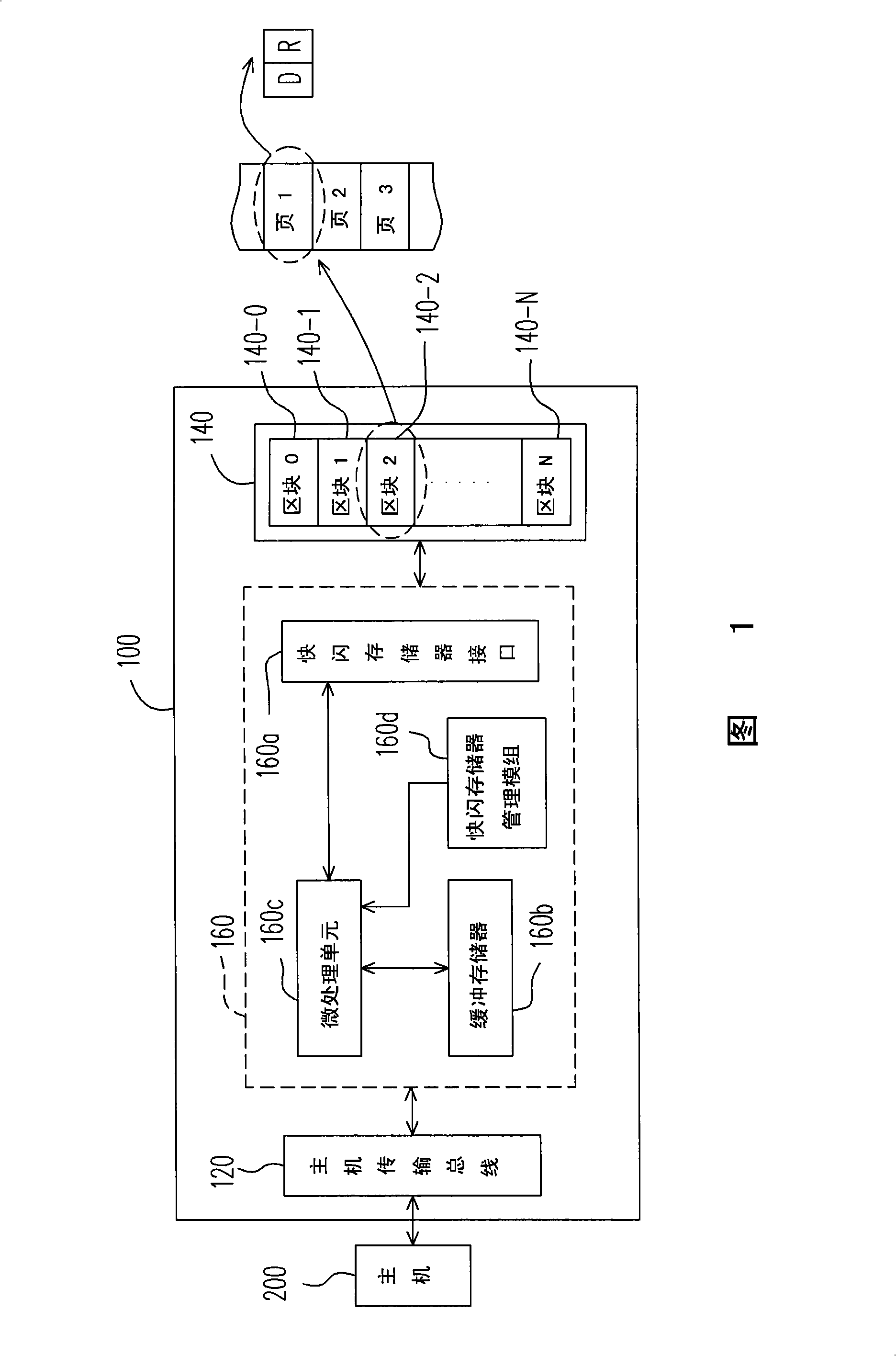
[0077] FIG. 1 is a block diagram illustrating a storage device with multiple storage modes according to a first embodiment of the present invention.

[0078] Referring to FIG. 1 , the flash memory storage device 100 includes a host bus 120 , a multi-level cell (Multi Level Cell, MLC) NAND flash memory 140 and a flash memory controller 160 .

[0079] The host bus 120 is electrically connected to the flash memory controller 160 and used for communicating with a host 200 . In other words, the host 200 can access the flash memory storage device 100 through the host bus 120 . In more detail, the host 200 can store data in the flash memory storage device 100 via the host bus 120, or read data from the flash memory storage device 100 and store it in the flash memory storage device 100 via the host bus 120. data of. In the embodiment of the present invention, the specification of the host bus 120 is a USB interface. But it must be understood that the present invention is not limite...

no. 2 example

[0107] The hardware structure and the operation of the flash memory of the second embodiment of the present invention are the same as those of the first embodiment (as shown in FIGS. 1 , 2 , 3 , 5 , 6 and 7 ), so the description will not be repeated here. The difference between the second embodiment and the first embodiment is that the storage mode of the storage mode switching method in the second embodiment further includes a mixed mode.

[0108] Figure 8 It is a flow chart illustrating a storage mode switching method according to the second embodiment of the present invention.

[0109] Please refer to Figure 8 , Figure 8and the flowchart shown is essentially the same as the Figure 4 The flow chart shown, the difference is that step S803 is compared to Figure 4 Step S403 further includes determining that the storage mode to be changed is a mixed mode. And in step S809, the storage mode is switched to the mixed mode, wherein the mixed mode means that some blocks in ...

no. 3 example

[0112] The hardware structure and the operation of the flash memory of the third embodiment of the present invention are the same as those of the first embodiment (as shown in FIGS. 1 , 2 , 3 , 5 , 6 and 7 ), so the description will not be repeated here. The difference between the third embodiment and the second embodiment is that the second embodiment also includes a mechanism for judging whether the user wants to keep the existing data in the storage device in the storage mode switching method.

[0113] Figure 9 It is a flow chart illustrating a storage mode switching method according to the third embodiment of the present invention.

[0114] Please refer to Figure 9 , in step S901 the flash memory storage device 100 receives a storage mode change command. In the embodiment of the present invention, the mode change command of the storage mode is transmitted through an application program installed on the host 200 . Specifically, when the flash memory storage device 100 ...


PUM


Abstract

The invention discloses a flash memory storage device which comprises a multilevel memory unit NAND flash memory, a flash memory controller and a host transfer bus. The multilevel memory unit NAND flash memory is provided with a plurality of blocks to store data, wherein, each block consists of an upper page and a lower page and the writing speed of the lower page is faster than the writing speed of the upper page. The flash memory controller is electrically connected with the multilevel memory unit NAND flash memory and is used for controlling the operation of the flash memory storage device and executing the switching method of the memory models. The host transfer bus is electrically connected with the flash memory controller and is used for communicating with the host. The flash memory storage device provided by the invention can provide a plurality of memory models so as to meet the storage demands of users for different data.

Description

technical field [0001] The present invention relates to a storage device, and in particular to a storage device with multiple storage modes, a flash memory controller and a switching method thereof. Background technique [0002] The rapid growth of digital cameras, cell phone cameras and MP3 players over the past few years has led to a rapid increase in consumer demand for storage media. Because Flash Memory (Flash Memory) has data non-volatility, power saving, small size and no Features such as mechanical structure are suitable for portable applications, and are most suitable for use in such portable battery-powered products. In addition to the built-in memory needs of portable products, for external products such as small memory cards and flash drives, each person may have multiple flash drives and small memory cards at the same time, so the market size is larger than those devices. Therefore, the flash memory industry has become a very popular part of the electronics ind...

Claims


Application Information

Patent Timeline
Patent Type & Authority Applications(China)
IPC IPC(8): G11C16/10
Inventor 叶志刚李智仁
Owner EMTOPS ELECTRONICS CORP
Why Eureka
Try Eureka