
Split joint type communication cabinet

A splicing and communication technology, which is applied in the field of communication cabinets, can solve problems such as the difficulty of changing the subdivision structure, large stress deformation of the welding structure, and rising temperature inside the cabinet, and achieves easy on-site engineering installation, high strength and stability, and maintenance-saving The effect of fees

Inactive Publication Date: 2009-07-29
ZTE CORP SHENZHEN CITY
View PDF0 Cites 22 Cited by
  • Summary
  • Abstract
  • Description
  • Claims
  • Application Information

AI Technical Summary

Problems solved by technology

[0003] One is that the stress deformation of the welded structure is large, the dimensional accuracy is not high, the assembly is difficult, and the production efficiency is low;
[0004] The second is that when used outdoors, the heat insulation effect is poor, the internal temperature of the cabinet tends to rise with the external temperature, and the heat dissipation energy consumption in the cabinet is high;
[0005] The third is that the airtight performance is not ideal, and the anti-corrosion, anti-salt spray, and anti-humidity capabilities are not good enough;
[0006] The fourth is that some cabinets installed in urban streets, once accidentally damaged, even if it is a small local damage, it is difficult to repair, and the entire cabinet must be replaced;
[0007] Fifth, the position of the door panel is limited by the welding structure, which makes it difficult to change the subdivision structure inside the cabinet. Once the cabinet is finalized, it is not easy to remodel, and it is difficult to achieve product diversification;
[0008] Sixth, the engineering installation accessories provided by general manufacturers are neither convenient nor durable;
[0009] Seventh, the screws exposed on the outside of the cabinet are easy to be used by individuals to deliberately damage the cabinet.

Method used


Image

  • Split joint type communication cabinet
  • Split joint type communication cabinet
  • Split joint type communication cabinet

Examples


Embodiment Construction

[0038] Below in conjunction with accompanying drawing and specific embodiment the present invention is described in further detail:

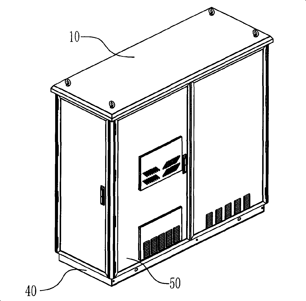
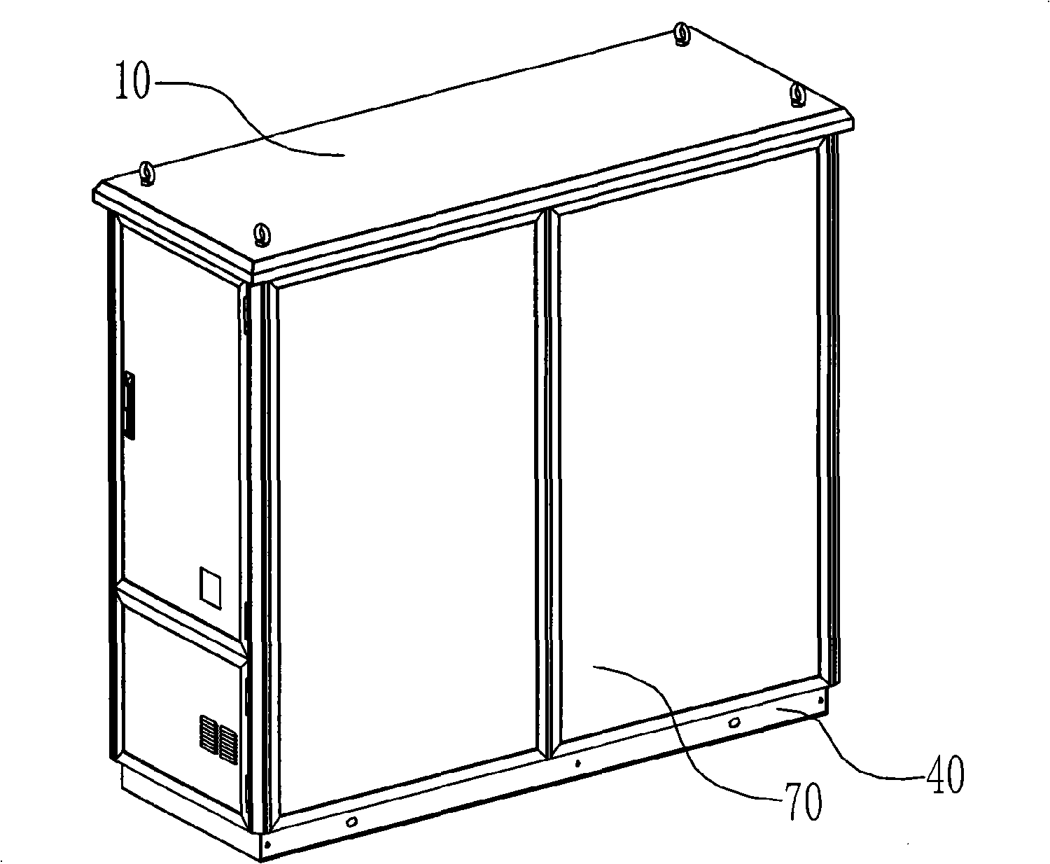
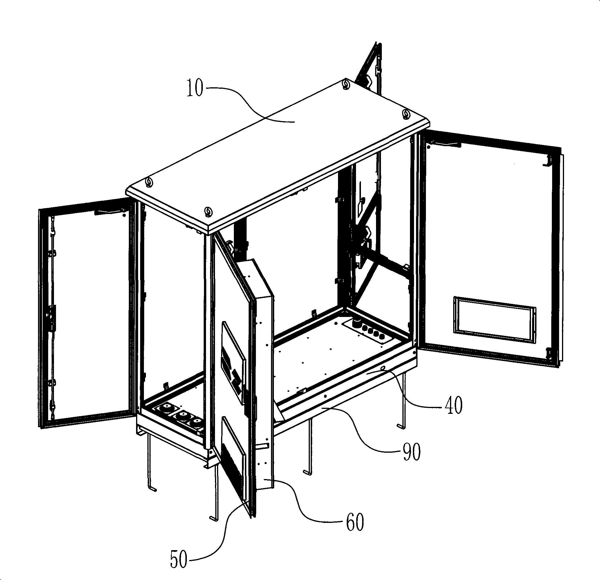
[0039] Such as figure 1 , figure 2 , image 3 , Figure 4 As shown, the spliced ​​communication cabinet includes a frame 20 and an outer cover, and the outer cover includes a top cover 10, a bottom plate 30, a base 40, a door panel 50, and a side plate 70; after the bottom plate 30 is fixed to the bottom of the frame 20 through a screw connection, the frame The bottom of the frame 20 is fixed to the base 40 through a threaded connector, and the top cover 10 is fixed to the top of the frame 20 through a threaded connector, so that the top cover 10 and the bottom plate 30 cover the top and bottom surfaces of the frame 20; and threaded connectors (see Figure 10 ) is embedded and connected to the frame 20, one side of the door panel 50 is hinged on the frame 20 through a hinge 501, and the other side is provided with a door lock 502 for lockin...


PUM


Abstract

The invention discloses a splicing type communication rack, which comprises a frame and a exterior cover member; the frame is mainly composed of section bar made columns and crossbeam by jointing them by fastening and connecting members; the exterior cover member comprises a top-cap, a base plate, a base seat, a door plate and a side plate; the base plate is fixed on the back of the frame bottom by fastening and connecting members; the framework bottom is fixed on the base seat by fastening and connecting members; the top-cap is fixed on the top of the frame bottom by fastening and connecting members; the top-cover and base plate covers the top surface and the bottom surface of the frame; the side plate is embedded on the frame by fastening and connecting members; one side of the door plate is hinged on the frame, the other side is equipped with door lock for locking the machine cabinet; and the door plate and the side plate cover the sides of the frame. The invention adopts section bar jointed frame structure and jointed integral body structure, which has higher dimension precision than the current steel plate welded structure, and achieves the advantages of small stress deformation, easy processing, convenient assembling and high production efficiency.

Description

technical field [0001] The invention relates to a communication cabinet, in particular to a spliced ​​communication cabinet. Background technique [0002] At present, the overall frame and the surrounding side panels (or door panels) of the outdoor communication cabinets produced by domestic manufacturers are generally welded by steel plates, and the heat insulation layer is fixed inside the welded side panels (or door panels) for heat insulation. There are some deficiencies in this welded structural form as follows: [0003] One is that the stress deformation of the welded structure is large, the dimensional accuracy is not high, the assembly is difficult, and the production efficiency is low; [0004] The second is that when used outdoors, the heat insulation effect is poor, the internal temperature of the cabinet tends to rise with the external temperature, and the heat dissipation energy consumption in the cabinet is high; [0005] The third is that the airtight perfor...

Claims


Application Information

Patent Timeline
IPC IPC(8): H05K7/18H05K5/00
Inventor 吉海青胡兴胜谢爱明王金山李西前龚林科特·纽芬爱格刘汉华
Owner ZTE CORP SHENZHEN CITY
Learn More