Calcination equipment for producing photocatalyst material

A photocatalyst and calcination technology, which is applied in the direction of catalyst activation/preparation, physical/chemical process catalyst, lighting and heating equipment, etc. It can solve the problems of failing to keep up with product quality requirements, unstable product quality, and poor continuous production. Achieve the effects of saving energy and manpower, high production continuity, and reducing production energy consumption

Inactive Publication Date: 2009-08-05
莱阳子西莱环保科技有限公司
View PDF0 Cites 2 Cited by
  • Summary
  • Abstract
  • Description
  • Claims
  • Application Information

AI Technical Summary

Problems solved by technology

[0002] According to a large number of current market research and product technology demonstrations in the same industry, all domestic and international enterprises that produce nano-titanium dioxide photocatalyst materials use relatively complicated equipment and processes. At present, the main calcination equipment used is muffle furnace, shuttle type Kilns, the products produced have shortcomings such as low photocatalytic efficiency, unstable product quality, low output, high energy consumption, and poor continuous production, which cannot keep up with the product quality requirements of the international market

Method used


Image

  • Calcination equipment for producing photocatalyst material
  • Calcination equipment for producing photocatalyst material
  • Calcination equipment for producing photocatalyst material

Examples


Embodiment 1

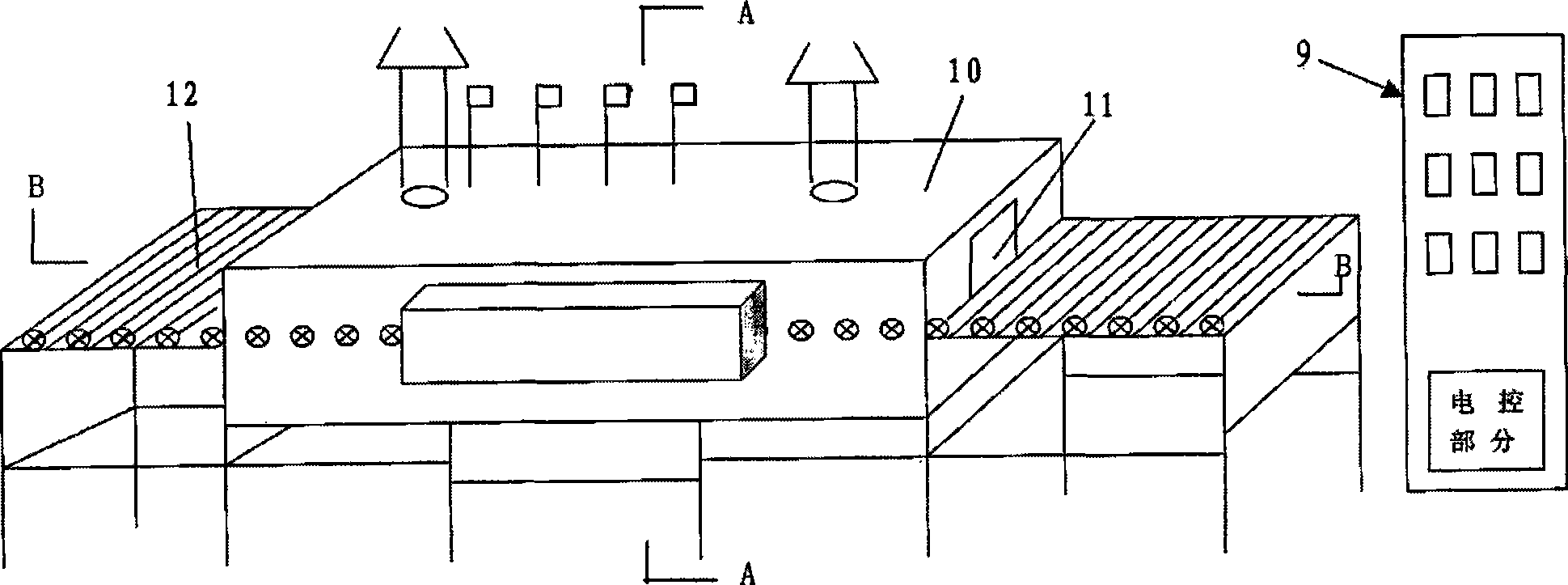
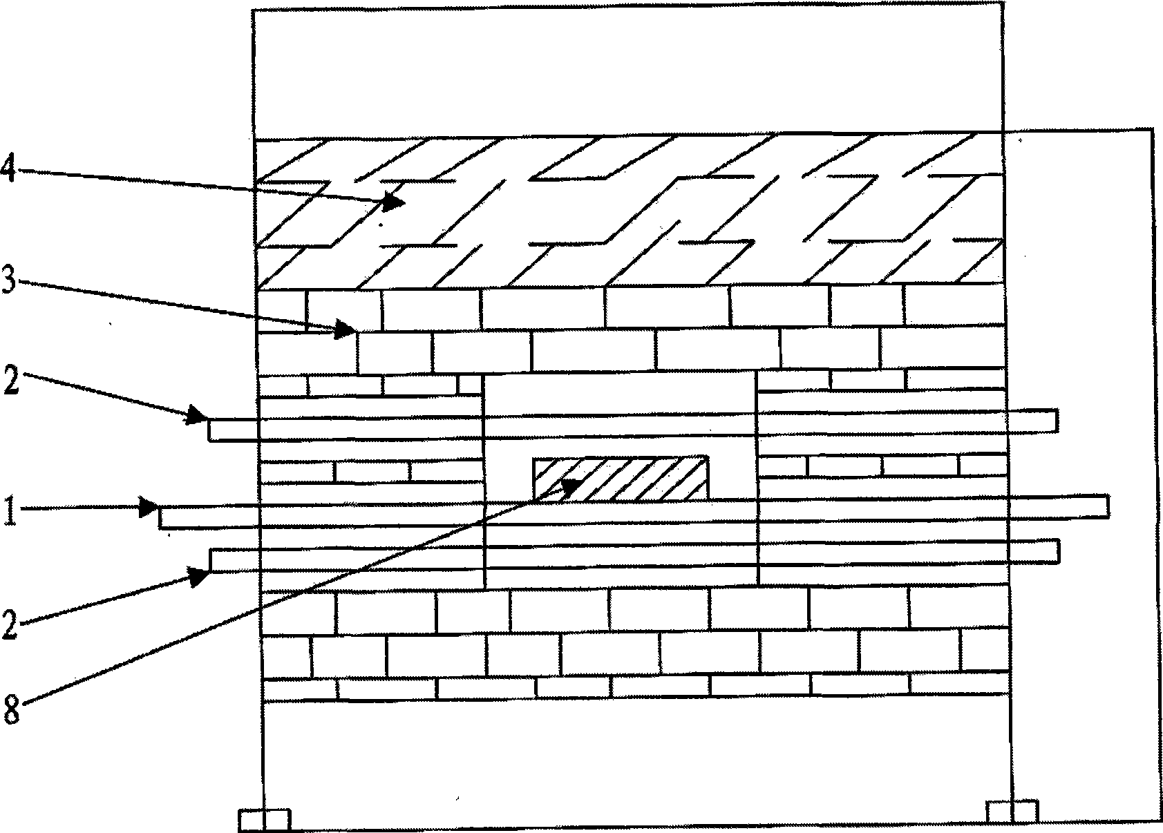
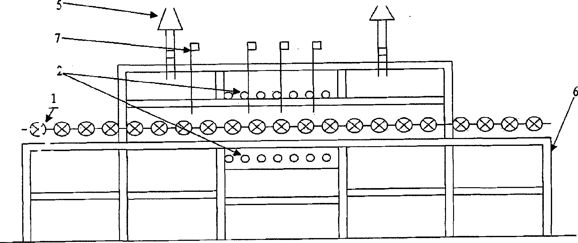
[0017] The calcination equipment reference of the production photocatalyst material of this embodiment Figure 1-4 , including the equipment support 6, on the upper end surface of the equipment support 6 is provided with a transmission roller table 12 laid by evenly distributed transmission sticks 1, on the top of the equipment support 6 is provided with a heating box 10, the transmission stick 1 runs through the heating In the box 10, the heating box 10 is provided with a transmission channel 11 along the direction of the transmission stick 1, and the upper and lower sides of the transmission stick 1 in the heating box 10 are provided with electrically heated silicon carbide rods 2 for heating. The outer layer of 2 is provided with thermal insulation brick 3, and thermal insulation material 4 is arranged on the outermost layer of heating box body 10, is connected with the electric heating silicon carbide rod 2 that is located at the outside electric control part 2 and carries ...


PUM


Abstract

The invention relates to calcining equipment for producing a photocatalyst material, which belongs to the technical field of calcinating equipment structures. The calcining equipment for producing the photocatalyst material comprises an equipment support 6, and is characterized in that the upper end surface of the equipment support 6 is provided with a live-roll table 12 spread by evenly distributed live rolls 1; a heater box body 10 is arranged above the equipment support 6; the live-rolls 1 pass through the inside of the heater box body 10; the heater box body 10 is provided with a transmission channel 11 along the direction of the live-rolls 1; the upper side and the lower side of each live-roll 1 inside the heater box body 10 are provided with an electric heating silicon carbide rod 2 used for heating respectively; an insulating brick 3 is arranged on the outer layer of the electric heating silicon carbide rod 2; and an insulating material 4 is arranged on the outmost layer of the heater box body 10. The equipment with arbitrarily adjusted temperature between 100 and 2,000 DEG C is applicable to calcination oxidation for different materials at different temperatures, and has the advantages of reasonable structure design, adjustable operating speed of between 0.01 and 1m / min in continuous running without outage, energy and manpower conservation, high stability and production continuity, product quality and yield improvement and energy consumption reduction.

Description

1. Technical field [0001] The invention relates to calcining equipment for producing photocatalyst materials, and belongs to the technical field of calcining equipment structures. 2. Background technology [0002] According to a large number of current market research and product technology demonstrations in the same industry, all domestic and international enterprises that produce nano-titanium dioxide photocatalyst materials use relatively complicated equipment and processes. At present, the main calcination equipment used is muffle furnace, shuttle type Kilns, the products produced have shortcomings such as low photocatalytic efficiency, unstable product quality, low output, high energy consumption, and poor continuous production, which cannot keep up with the product quality requirements of the international market. 3. Contents of the invention [0003] The purpose of the present invention is to solve the shortcomings of the above-mentioned prior art, to provide a reas...

Claims


Application Information

Patent Timeline
Patent Type & Authority Applications(China)
IPC IPC(8): B01J37/08F27B9/24F27B9/26F27B9/06F27B9/40
Inventor 王江彬
Owner 莱阳子西莱环保科技有限公司
Why Eureka
Try Eureka