Building combined type foundation, collar beam and combined frame composed of foundation and collar beam

A combined foundation and building technology, applied in building construction, infrastructure engineering, construction, etc., can solve the problems of long construction period, large amount of formwork, large amount of wet work, etc., and achieve great economic and social benefits, Widely popularized and used, the effect of short construction period

Inactive Publication Date: 2009-08-05
从卫民 +1
View PDF0 Cites 4 Cited by
  • Summary
  • Abstract
  • Description
  • Claims
  • Application Information

AI Technical Summary

Problems solved by technology

[0002] At present, most of the buildings are concrete frame structures, and the frame is mainly formed by integral pouring on site. This construction method requires a large amount of formwork, a large amount of wet work, and a high labor intensity for the operator. What

Method used


Image

  • Building combined type foundation, collar beam and combined frame composed of foundation and collar beam
  • Building combined type foundation, collar beam and combined frame composed of foundation and collar beam
  • Building combined type foundation, collar beam and combined frame composed of foundation and collar beam

Examples


Embodiment 1

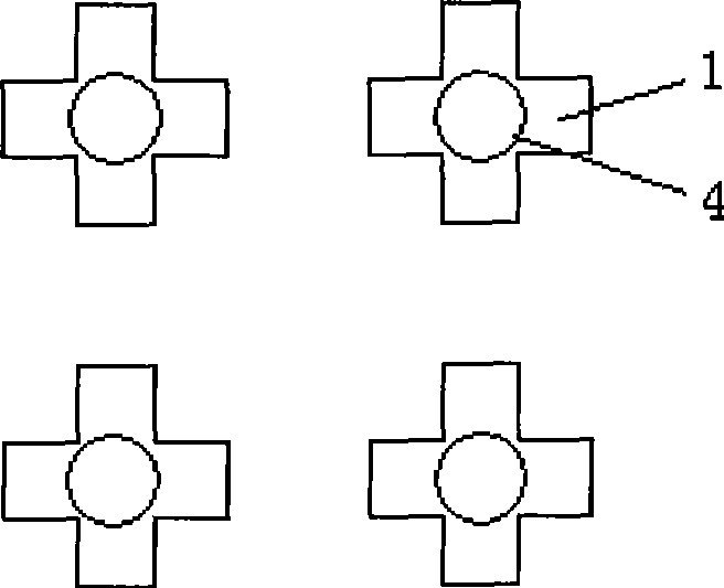
[0021] Such as figure 1 As shown, the combined building foundation of the present invention is composed of four cross-shaped concrete members 1. The cross center of the cross-shaped member 1 is provided with a ring beam, beam and column connection device, and the beam and column connection device is a connection device. The column shoe 4 and the connecting column shoe 4 are round pipes or square pipes made of metal material (a round pipe is selected in this embodiment), and the lower end of the column shoe 4 is inserted into the cross-shaped concrete component when the component is prefabricated. Such as Figure 5 As shown, a connecting hole c41 is provided on the side wall of the connecting column shoe 4, and the connecting hole c41 communicates horizontally.

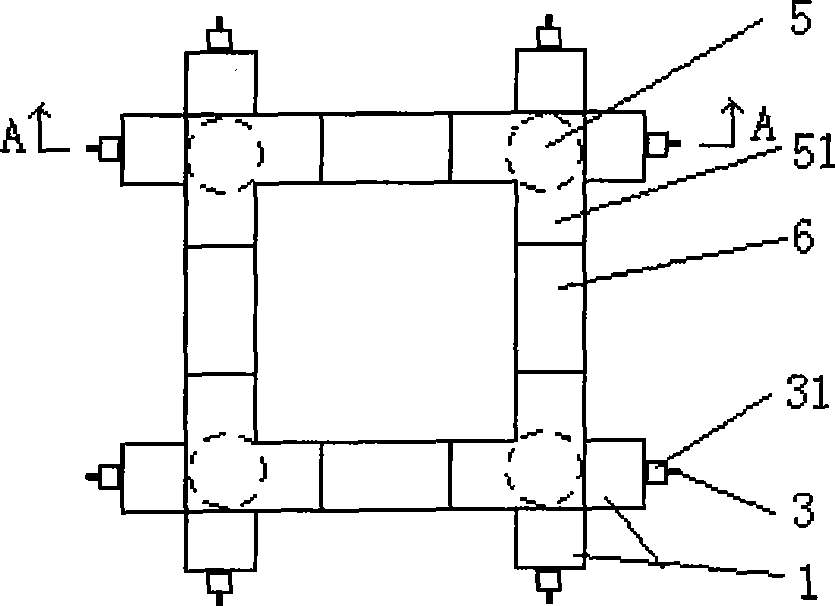
[0022] Such as figure 2 As shown, the building combined ring beam of the present invention is composed of four beams 5 and 6 whose planes are L-shaped upper connecting structures 51; figure 2 , 5 As shown, the connectin...

Embodiment 2

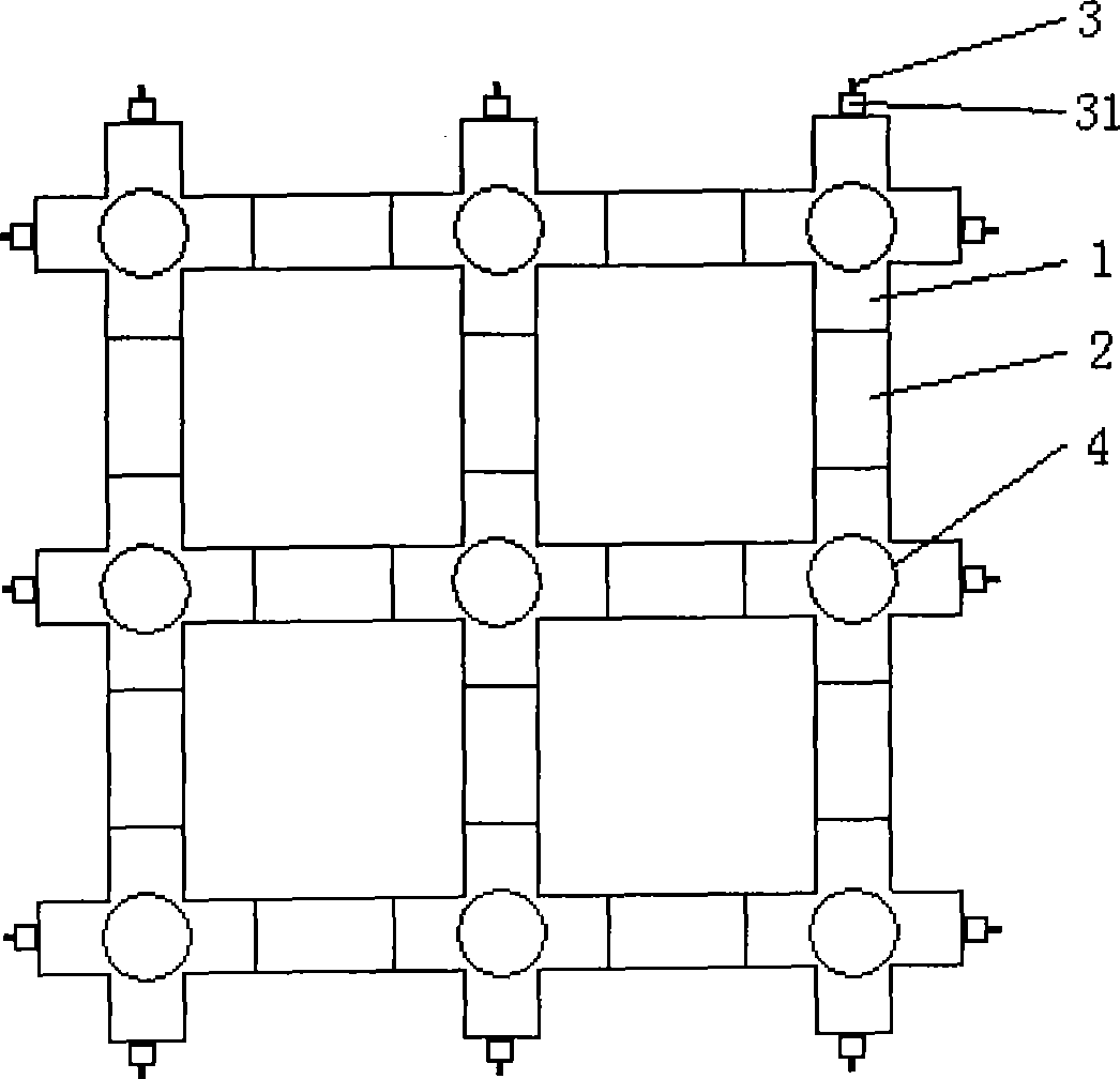
[0024] Such as image 3 As shown, the combined building foundation of the present invention is composed of nine cross-shaped concrete members 1 and a line-shaped member 2; image 3 , 6 As shown, the cross-shaped member 1 is provided with a through connecting hole a11 consistent with its cross, and the in-line member 2 is provided with a through connecting hole b22 that is parallel to the in-line shape and matched with the connecting hole a11, and the connecting object 3 passes through The connecting holes a11 and b22 are connected and fixed with a fastening head 31. Such as Figure 6 As shown, the joint end surface of the cross-shaped member 1 and the in-line member 2 is provided with a matching concave-convex surface, and the matching concave-convex surface is covered with a metal concave-convex part, and the metal concave-convex part and The anastomotic surface of the cross-shaped member 1, the in-line member 2 is provided with paws, and the paws of the concave and convex parts a...

Embodiment 3

[0026] Such as Figure 4 As shown, the building combined ring beam of the present invention is composed of nine upper connecting structures 51 with beams 5 and 6 whose planes are L-shaped, in-line, and cross-shaped, respectively; Figure 4 , 6 As shown, the connecting hole d52 is arranged parallel to the plane L-shaped, or in-line, or cross-shaped axis of the connecting structure 51, the beam 6 is provided with a matching connecting hole g61, and the connecting object 3 passes through the connecting holes d52, g61 for fastening Head 31 is connected and fixed; such as Figure 6 As shown, the beam column 5 is provided with a through connecting hole e53 parallel to the axis, the lower end surface of the beam column 5 is provided with a groove 55, the connecting hole e53 is connected to the groove 55, and the connecting object 3 is recessed from the lower end surface of the beam column 5. The groove 55 penetrates into the connecting hole e53 until it passes through the upper end of the...


PUM


Abstract

The invention discloses a combined type base of a building, a ring beam and a combined type shell frame formed by the bases and the ring beams. Each part is a concrete prefab standard element. When a house is built, the prefab standard elements only need to be carried to a jobsite and can be assembled into the shell frame according to the building requirements of the house. In the course of the assembly of the shell frame, the invention has no wet construction, and the labor intensity of an operator is low. More importantly, the construction period is greatly shortened. If a prefab lamella cast-in-situ superimposed hollow floor in a patent application submitted by the inventor previously is used, the wet construction in the course for building the house can be lowered to be the lowest, the construction period can be lowered to be the shortest, and especially when serious disasters and accidents happen, the house with the combined type shell frame structure has more outstanding advantages.

Description

Technical field: [0001] The invention relates to a building, in particular to a foundation, a ring beam, and a frame formed by the foundation and the ring beam. Background technique: [0002] At present, most of the buildings are concrete frame structures. The frame is mainly formed by on-site integral casting. This construction method requires a large amount of formwork, a large amount of wet work, and a high labor intensity of the operator. What is more prominent is the long construction period. Especially when encountering major disasters and accidents, this kind of frame structure house cannot meet the emergency requirements, but can only build temporary simple bungalows, which can be demolished when not in use. Summary of the invention: [0003] The technical problem to be solved by the present invention is to provide a combined foundation, combined ring beam and combined frame composed of the above-mentioned foundation and ring beam. This kind of frame can not only overcom...

Claims


Application Information

Patent Timeline
IPC IPC(8): E02D27/02E04B1/18E04B1/00
Inventor 从卫民
Owner 从卫民
Why Eureka
Try Eureka