U+I type ventilating system for top-coal caving face

A ventilation system and working face technology, which is applied in the ventilation of mines/tunnels, ground mining, mining equipment, etc., can solve the problem of poor reliability of gas discharge, reduction of wind flow capacity and radius of effective gas discharge, brackets and enclosures. Rock collapse and other problems, achieve reliable technical guarantee, eliminate spontaneous combustion of floating coal, and eliminate gas and coal dust explosions

Inactive Publication Date: 2009-08-05
TAIYUAN UNIV OF TECH
View PDF2 Cites 29 Cited by
  • Summary
  • Abstract
  • Description
  • Claims
  • Application Information

AI Technical Summary

Problems solved by technology

[0009] ① Arrangement of staggered return air troughs in the gas lane on the top floor, some in the middle of the working face, and some internal staggered return air troughs of 15-20m, which leads to the inability to effectively discharge the upper working face, upper corner and the upper part of the corresponding goaf Gas accumulated in space
[0010] ② Located in the concentrated stress area and plastic failure area of ​​the coal body in front of the working face, the support and surrounding rock (coal) of the top gas roadway are prone to collapse, and the ventilation section is blocked, so that the air flow capacity of the roadway and the radius of the effective gas discharge are greatly reduced. decrease, the reliability of its exhaust gas becomes worse
[0011] ③ When the top coal is thin, it is easy to cause roof leakage above the support under the top gas lane, which affects the normal production of the working face and is not conducive to safe production

Method used


Image

  • U+I type ventilating system for top-coal caving face
  • U+I type ventilating system for top-coal caving face

Examples


Embodiment Construction

[0029] Specific embodiments of the present invention will be described in detail below in conjunction with the accompanying drawings.

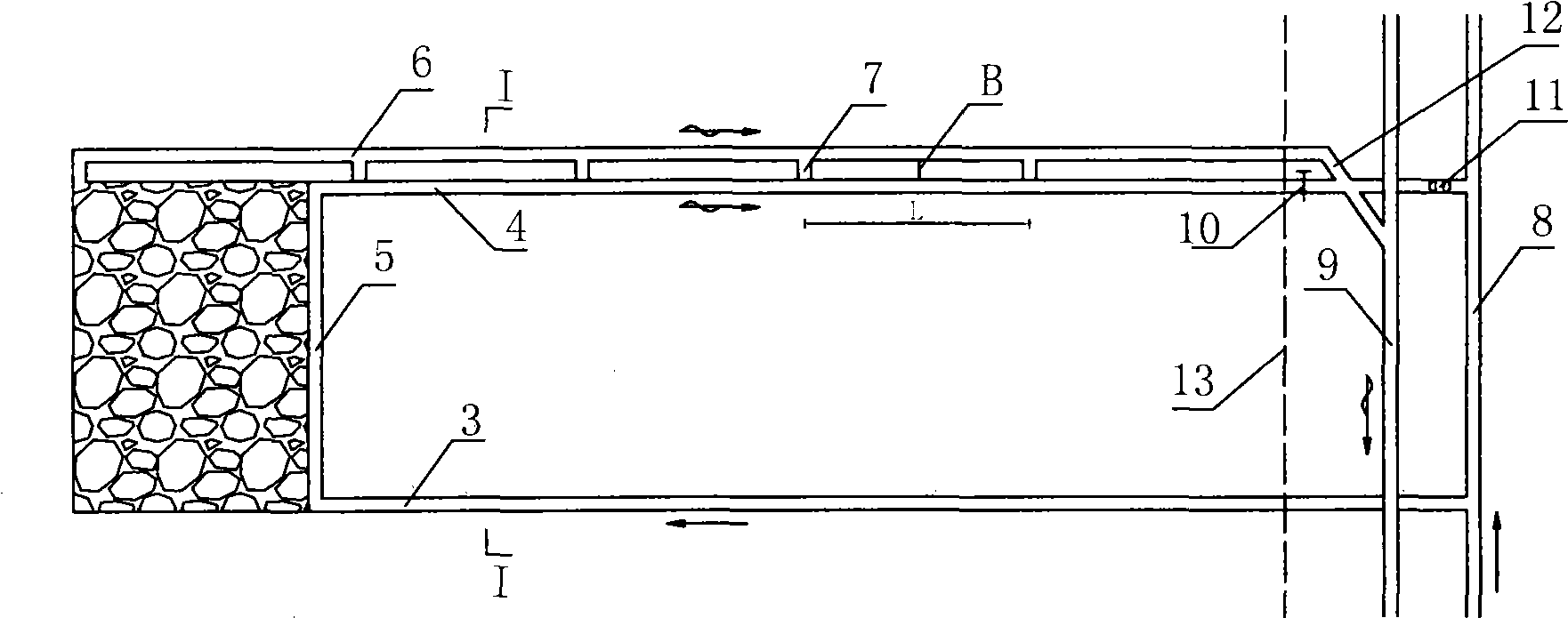
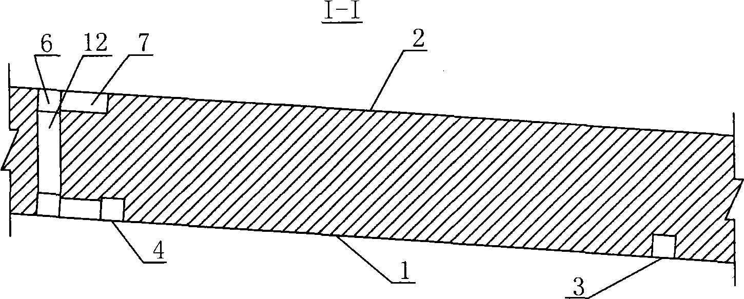
[0030] Such as figure 1 and figure 2 Shown, the schematic diagram of the U+I type ventilation system of the top-coal caving face of the present invention. The U+I ventilation system of the top-coal caving face includes the following parts:

[0031] 1. The air inlet trough and the return air trough of the top coal caving face are arranged along the coal seam floor, and are respectively connected with the air inlet and return air lanes of the mining area (or mine), and are connected with the inlet air trough on the bottom return air chute. The air door 11 is arranged near the connection of the wind lane, thereby forming the basic ventilation system for coal mining production at the bottom of the top coal caving face.

[0032] 2. In the return air trough on the bottom floor, a horizontal connection roadway is excavated to the outside of the w...


PUM


Abstract

The invention provides a U+I type ventilation system for a work surface of top coal caving, which is an improvement of the arrangement of the U type, the U+L type and the E type or B type laneways and the ventilation systems in the prior art. An air intake way and an air return way of the work surface of top coal caving are arranged along a bottom board of a coal bed, and a regulation air door is arranged on the part of the air return way close to a big air return lane to control the reasonable ventilating parameter of the U+I type ventilating system. The invention is mainly characterized in that air exhausting lanes of top boards are arranged in parallel along the air return way with the parallel outward-staggered distance of 0 m to 5 m from the air return way to form the U+I type ventilating system of a one-intake and two-return mode. The invention fundamentally solves the problem of the accumulation of gas and coal dust on the upper section, the upper spatial angle and the gob area of the work surface of top coal caving, in particular the problem of the accumulation of the gas and the coal dust of the upper space of the upper gob area, provides a safe and high-effect ventilating system, and creates an excellent mechanical environment for realizing the exploitation of the top coal caving of small coal pillars and increasing the recovery rate of coal.

Description

technical field [0001] The invention relates to a roadway layout method for top-coal caving mining in thick coal seams, which belongs to the technical field of top-coal caving mining in thick coal seams, and in particular to an improvement of the position of a roof exhaust roadway in a top-coal caving working face. Background technique [0002] At present, more than 90% of the thick coal seams above 5m are mined by top-coal caving method. This method of top-coal caving mining also has shortcomings, such as a lot of coal loss, low coal recovery rate, etc., especially gas, coal dust, Spontaneous combustion of coal still poses a serious threat to the safe production of the top coal caving face. Designing a reasonable air supply volume and ventilation system is one of the most effective ways to solve gas, coal dust and coal spontaneous combustion in the top coal caving face. In order to realize the safe production of the top-coal caving face, the ventilation system of the top-c...

Claims


Application Information

Patent Timeline
Patent Type & Authority Applications(China)
IPC IPC(8): E21F1/00E21F1/10E21C41/16
Inventor 康天合杨永康王开柴肇云王东李义宝鲁伟高鲁刘忠峰
Owner TAIYUAN UNIV OF TECH
Why Eureka
Try Eureka