Flue gas sampling probe

A sampling probe and flue gas technology, applied in sampling devices and other directions, can solve problems such as easy corrosion, easy thread corrosion, inconvenient maintenance, etc., and achieve the effects of prolonging the maintenance period, improving the degree of purification, and stable and reliable operation.

Active Publication Date: 2009-08-05
广东盈峰科技有限公司
View PDF0 Cites 39 Cited by
  • Summary
  • Abstract
  • Description
  • Claims
  • Application Information

AI Technical Summary

Problems solved by technology

[0004] One situation is: the sampling pipe is built in the flue or chimney, the sampling pipe is connected to the sampling probe (filter front end), the filter is placed in the sampling probe, the filter shell is electrically heated and kept warm, and the back blowing air is compressed air. The blowing method is to blow from the inside of the filter element to the outside, and the reverse blowing airflow flows into the flue or chimney against the direction of the sampling airflow. In this case, there are the following problems: in practical applications, due to the low temperature of the compressed air, the temperature of the filter element, sampling tube, and filter shell decreases during backflushing. , when re-sampling, when the high-temperature flue gas meets the low-temperature sampling probe parts, water will condense and form a mixture with the smoke to block the filter element. The smoke and dust in the filter and sampling pipe cannot be blown clean, and it will be blocked after a long time. Since the rear end cover of the filter is connected with the filter housing in a threaded manner, water will condense after backflushing, and corrosive gases such as SO2 will be added. Function, the thread part is easy to rust, it is difficult to disassemble when replacing the cleaning filter element, and the maintenance is extremely inconvenient
[0005] Another situation is: the sampling pipe is built in the flue or chimney, the sampling pipe is connected to the sampling probe (filter front end), the filter is placed in the sampling probe, the filter shell is electrically heated and kept warm, and the back blowing gas is compressed by heating. Air, there is a special compressed air heating tank. The back blowing method is to blow from the inside of the filter element to the outside. The back blowing airflow flows into the flue or chimney against the direction of the sampling airflow. The filter element is connected to the rear end cover of the filter through threads. The rear end cover is pressed against the rear end of the filter housing by means of a lever, and acts as a seal. In this case, there are the following problems in practical applications. After the back blowing air passes through the high-density filter element, the air flow rate decreases, and the filter 1. The smoke and dust in the sampling tube cannot be blown clean, and it will be blocked after a long time. At the same time, because a special compressed air heating tank is used, the temperature of the compressed air must be kept at all times, and a temperature control device is required, which consumes a lot of energy , 24 hours a day consumes about 10 degrees of electricity, and increases the technical requirements for the production of compressed air tanks, increasing the production cost
[0006] At present, most of them use ceramic filter elements, which are not effective for soaking, cleaning and reusing. The parts and components in contact with flue gas are generally made of 304 stainless steel, and the concentration of corrosive gases (such as SO2, SO3, HCL, etc.) is relatively high. time, vulnerable to corrosion, short service life, mostly in 1-2 years

Method used


Image

  • Flue gas sampling probe
  • Flue gas sampling probe
  • Flue gas sampling probe

Examples


Embodiment Construction

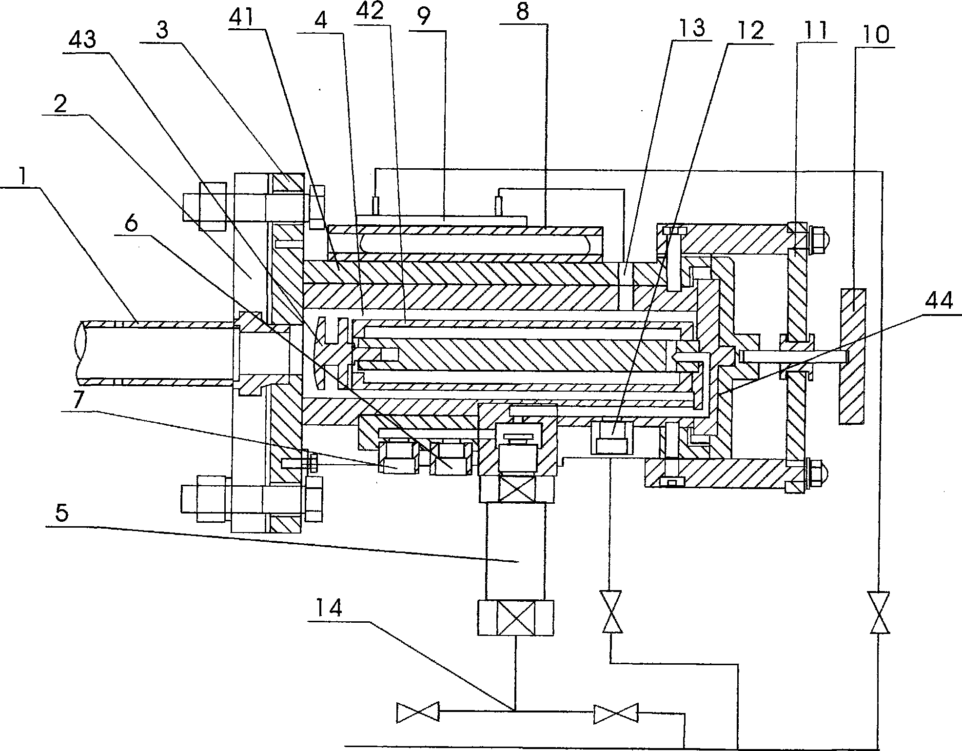
[0018] The present invention will be further introduced below in conjunction with the accompanying drawings and specific embodiments, but not as a limitation of the present invention.

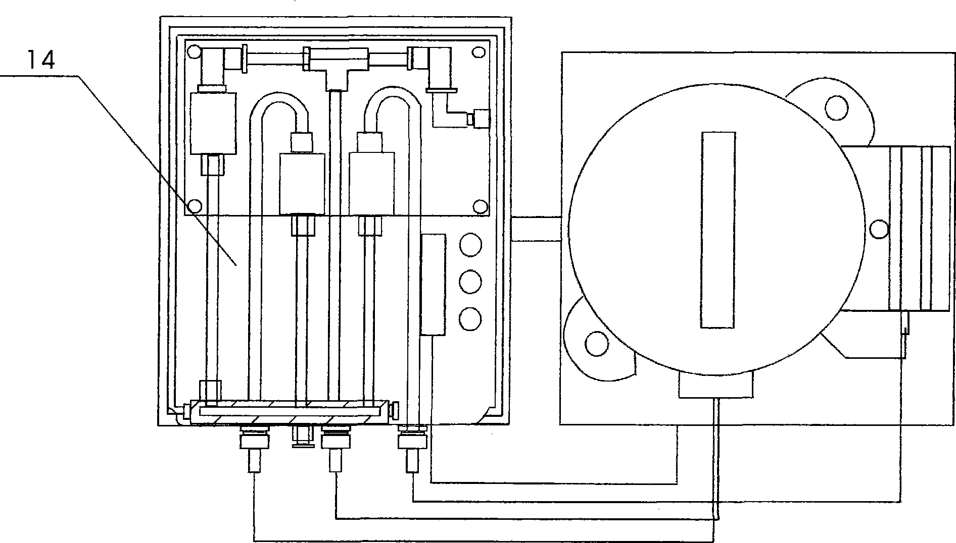
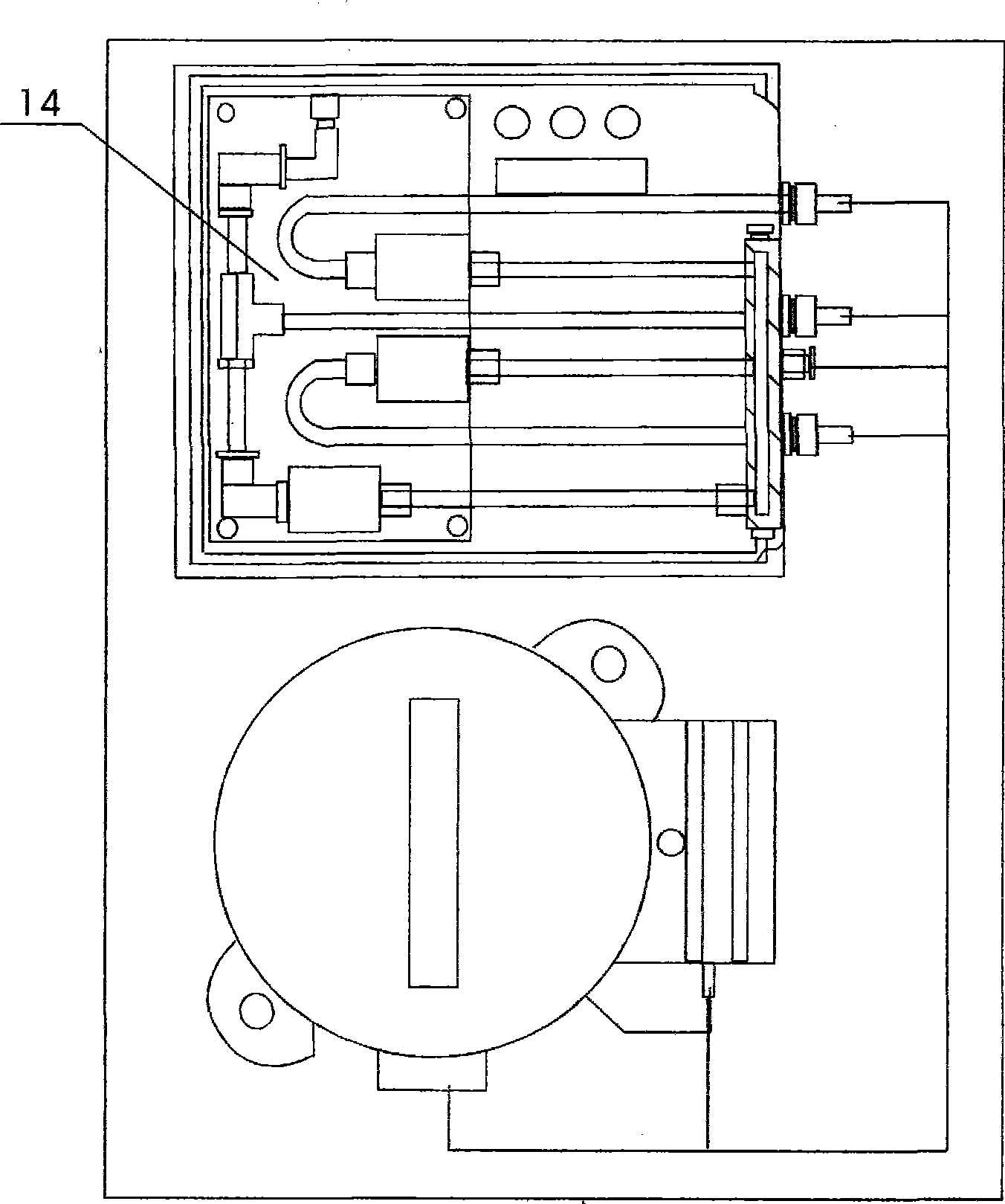
[0019] As shown in the figure, the present invention mainly includes a sampling pipe 1, a sampling flange 2, a sampling probe mounting plate 3, a filter 4, a cylinder 5, a standard air inlet 6, a sample gas outlet 7, an electric heater 8, and a blowback The air heater 9, the jacking screw 10, the lever 11, the inner back-blowing air port 12, the outer back-blowing air port 13 and the electrical air circuit 14 are characterized in that the sampling pipe 1 and the sampling probe mounting plate 3 are connected in a threaded manner, and the sampling The flange 2 and the sampling probe mounting plate 3 are fixedly connected by bolts, the filter 4 and the sampling probe mounting plate 3 are fixed together, the electric heater 8 and the blowback air heater 9 are all installed on the filter housing 41, ...


PUM


Abstract

The invention relates to a fume sampling probe which mainly consists of a sample pipe, a sample flange, a sample probe mounting plate, a filter, an air cylinder, a standard air inlet, a sample gas outlet, an electric heater, a backblowing air heater, a puller screw, a lever, an internal backblowing hole, an external backblowing hole, a temperature probe, a temperature controller, an electromagnetic valve, a gas-type fitting, a case body and an electrical gas circuit. The invention has the advantages that filter elements of the filter made of resistant material are changed and clean for use alternately, a special backblowing technology method is realized through the electrical gas circuit, the energy consumption is saved, the backblowing effect is good, only one maintenance is needed in one year, the heating temperature can be randomly set, the automatic backblowing period and time can be freely set according to the on-site fume condition, the service life is long, the running is stable and reliable, and the running cost is low, thereby being widely applied to a fume discharge continuous monitoring system of a fixed pollution source in the fume sampling and processing field.

Description

technical field [0001] The invention relates to a flue gas sampling probe. Background technique [0002] With the development of society, the advancement of science and technology, and the development of large industries, the requirements for environmental protection are getting higher and higher. Real-time monitoring and real-time processing are required. Therefore, the continuous emission monitoring system of fixed pollution sources is particularly important, and the flue gas of fixed pollution sources The flue gas sampling probe of the continuous emission monitoring system plays a pivotal role in the whole system. The flue gas in the chimney or flue is sucked by the sampling pump (equipment other than the probe), heated and kept warm by the flue gas sampling probe, filtered and dedusted In order to meet the requirements of high-precision flue gas primary filtration and heat preservation, and then go through the electric heating pipe (a kind of electric heating and constan...

Claims


Application Information

Patent Timeline
Patent Type & Authority Applications(China)
IPC IPC(8): G01N1/22
Inventor 李野
Owner 广东盈峰科技有限公司
Why Eureka
Try Eureka