Chip film cutting apparatus

A film device and chip technology, applied in lamination auxiliary operations, metal processing, electrical components, etc., can solve the problems of inconvenient process utilization, inability to adapt to the demand that the film is smaller than the chip, and does not meet cost considerations, etc.

Inactive Publication Date: 2009-08-05
C SUN MFG
View PDF2 Cites 15 Cited by
  • Summary
  • Abstract
  • Description
  • Claims
  • Application Information

AI Technical Summary

Problems solved by technology

[0006] However, this existing method utilizes the circular blade on the outer periphery of the chip, and uses the lower piston rod positioned at the center to carry the chip to move the chip and the film downwards, and cooperates with the downward movement of the upper piston rod to cut the film, but because the blade is It is located on the outer periphery of the chip, so the cut film must be larger than the chip, and it cannot meet the requirement that the film is smaller than the chip, and the circular blade of this existing equipment is set on the outer periphery of the lower piston rod that carries the chip, so if It is very complicated to change the size of the circular blade, which is not easy to use in the process
[0007] Furthermore, the above two existing methods can only complete the film cutting and film attachment of one unit of chips at a time, so the overall production capacity is bound to be limited. If a large number of machines are purchased to produce the same process, the cost is very high, which does not meet the cost considerations

Method used


Image

  • Chip film cutting apparatus
  • Chip film cutting apparatus
  • Chip film cutting apparatus

Examples


Embodiment Construction

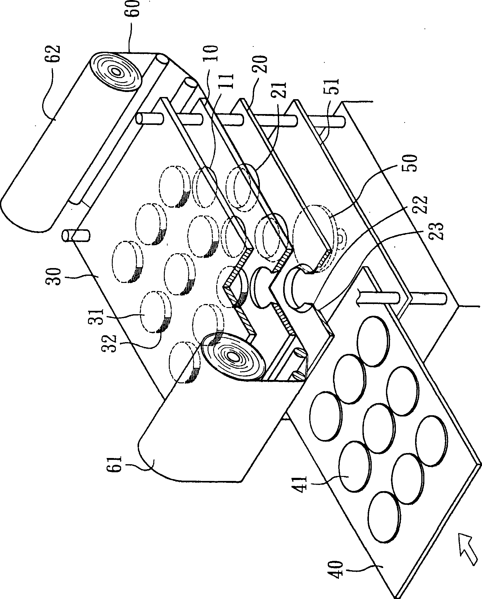
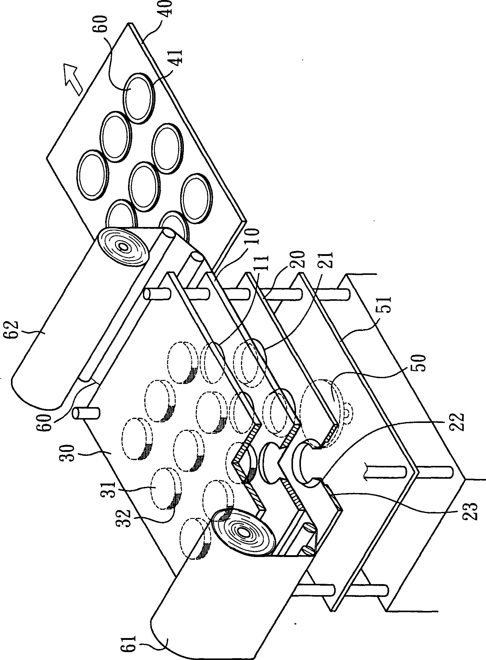
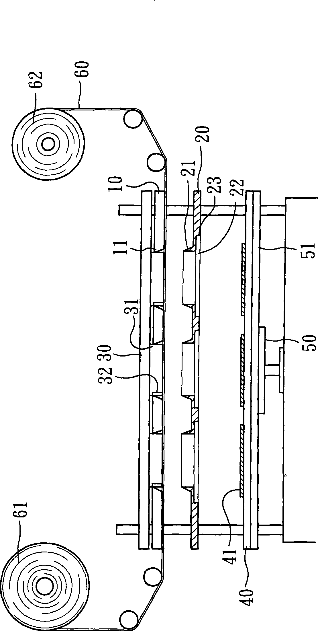
[0025] The present invention relates to a chip cutting device, please refer to figure 1 and figure 2 As shown, it is provided with a film punching upper seat 10, a film punching lower seat 20, a film output unit 61, a film receiving unit 62 and a carrying unit 40, wherein:

[0026] The punching upper seat 10 is arranged above the punching lower seat 20 and is in a fixed state. The punching upper seat 10 is provided with several upper knife seats 11, and the upper knife seats 11 are arranged on the lower end surface of the punching film upper seat 10 and are concave. Circular opening structure, and the inner diameter width of the lower end surface of the inner wall of the upper knife seat 11 is greater than the inner diameter width of the upper end surface; the punching lower seat 20 is a structure that can move up and down, and the punching lower seat 20 is provided with several lower knife seats 21 , the lower knife seat 21 is a protruding circular opening-shaped structure ...


PUM


Abstract

A chip membrane-cutting device is provided with a membrane-punching upper seat, a membrane-punching lower seat, a membrane-out unit, a membrane-receiving unit and a bearing unit, wherein, the membrane-punching upper seat is provided with a plurality of upper tool holders, the membrane-punching lower seat is provided with a plurality of lower tool holders, and the inner diameter of the lower tool holder is less than or equal to the diameter of a chip; the membrane-out unit and the membrane-receiving unit are respectively arranged at the two sides of the membrane-punching upper seat and the membrane-punching lower seat, thereby leading the membrane body to be rightly arranged between the membrane-punching upper seat and the membrane-punching lower seat; the upward side of the membrane-punching upper seat is provided with an adsorption disk corresponding to the upper and lower tool holders; the inner side of the adsorption disk is provided with at least one pre-paste unit, so the efficacy for cutting a membrane body with the area less than or equal to that of the chip is reached, a plurality of membrane bodies can also be simultaneously cut, and thus the efficacy for changing the cutting size can be achieved.

Description

technical field [0001] The invention relates to a film cutting device, in particular to a chip film cutting device which utilizes upper and lower die film seats located above the chip to cut the film so as to cut a film body larger than or equal to the area of ​​the chip. Background technique [0002] The existing chip cutting device uses a rectangular film material and attaches the film material to the chip, and then removes the excess part with a laser or a diamond knife. In order to prevent the laser or diamond knife from contacting the chip, the cut film material It is bound to be larger than the chip area, but in conjunction with the chip manufacturing process, it is necessary to reserve a circle around the chip without attaching the film material. Therefore, the existing technology uses exposure or development to remove excess film material, but this method increases the number of steps in the process and Cost, in order to improve this technology, the film material is ...

Claims


Application Information

Patent Timeline
Patent Type & Authority Applications(China)
IPC IPC(8): H01L21/00H01L21/02B26F1/38B32B38/04
Inventor 纪建州
Owner C SUN MFG
Why Eureka
Try Eureka