Capacitor induction type touch press-key and measuring method for touch press-key capacitor
A capacitive sensing and button technology, which is applied in the measurement of capacitive-sensing touch buttons and the capacitance of touch buttons, and in the field of electronic product control, can solve the problems of large output signal value error, easy wear of mechanical buttons, misoperation or immobility, etc., to achieve Improve reliability, low cost, and realize the effect of precise positioning
- Summary
- Abstract
- Description
- Claims
- Application Information
AI Technical Summary
Problems solved by technology
Method used
Image
Examples
Embodiment 1
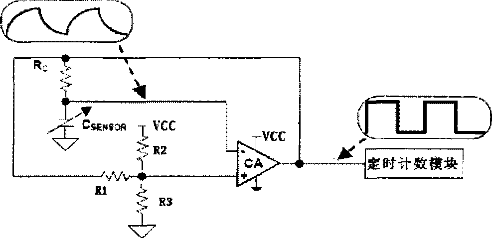
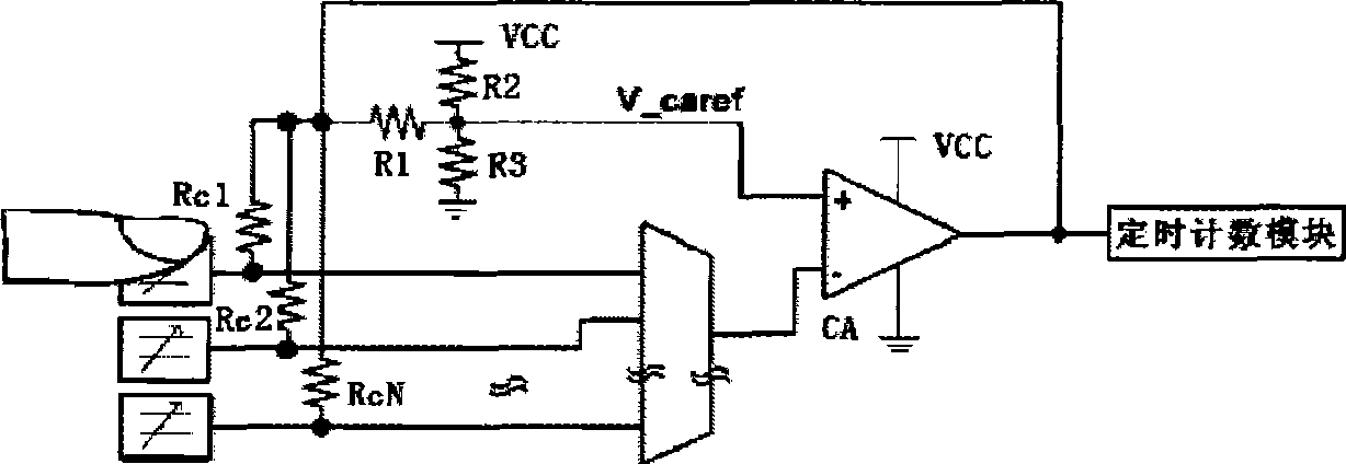
[0013] Embodiment 1: with reference to attached figure 1 with 2 . Capacitive sensing touch button, the shape of the touch button can be square, round, or bar. The touch buttons are distributed on the PCB printed circuit and are respectively connected to the negative signal input terminal of the comparator, the resistor R C (Resistance R C means R C1 ~R Cn ) connected at one end, R C The other end of R is respectively connected to the output end of the comparator, the signal end of the timing counting module and one end of the resistor R, and the other end of R is connected to the positive signal input end of the comparator. That is to say, 1 to n touch buttons are distributed on the PCB printed circuit and are respectively connected to the signal input terminals of the multi-channel analog switch by wires and connected to the resistor R respectively. C1 ~R Cn connected at one end, R C1 ~R Cn The other end is connected to R in the resistor ladder network 1 One end of...
Embodiment 2
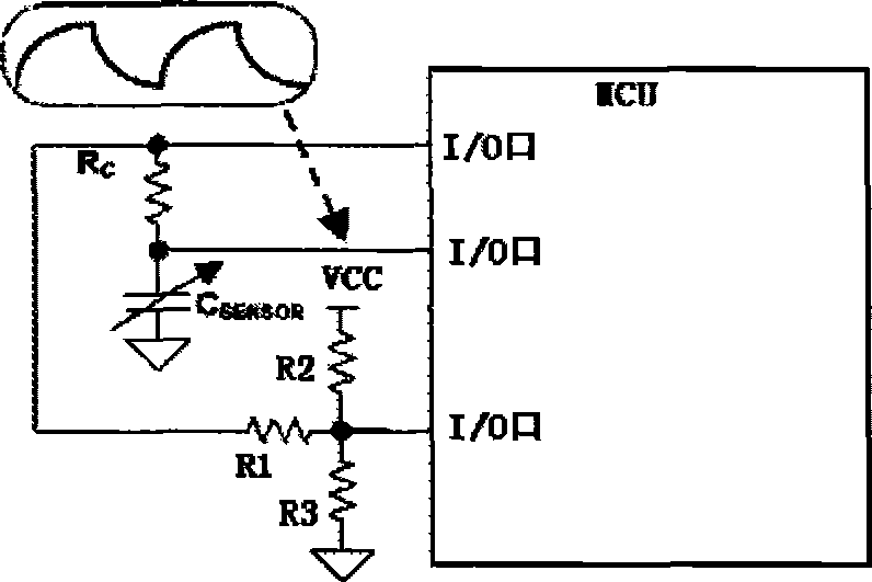
[0014] Embodiment 2: with reference to attached image 3 with 4 . On the basis of Embodiment 1, capacitive sensing type touch keys, the touch keys are distributed on the PCB printed circuit and are respectively connected to the signal input terminal of the MCU, the resistor R C connected at one end, R C The other end of the MCU is connected to the signal end of the MCU and R in the resistor ladder network 1 connected at one end, R 1 The other end of the resistor ladder network R 2 and R 3 One end and the signal end of the MCU, R 2 The other end is connected to the signal end of the MCU, R 3 The other end of the ground. 1~n touch buttons are distributed on the PCB printed circuit and use wires to connect with resistor R respectively. C1 ~R Cn connected at one end, R C1 ~R Cn The other end is connected to R in the resistor ladder network 1 One end of the MCU signal end, R 1 The other end of the MCU is connected to the signal end and R 2 , R 3 one end of the R 2 ...
Embodiment 3
[0015] Embodiment 3: On the basis of embodiment 1 or 2, the measuring method of capacitive sensing type touch key capacitance, comparator and PCB capacitive touch key form an oscillating circuit, the frequency of this oscillating circuit changes with the change of touch key capacitance, When the system is initialized, when no button is pressed, each touch button has its corresponding basic capacitance. The timing counting module or MCU records the oscillation frequency corresponding to the basic capacitance value of each touch button. When the finger is pressed on the touch button , the capacitance value of the touch button becomes larger, the frequency of the oscillating circuit becomes smaller, and the timing counting unit detects that the frequency of the oscillating circuit becomes smaller, confirming that the capacitive touch button has been pressed, that is, the PCB touch button and the comparator are connected as shown in the figure , using the capacitance of the PCB tou...
PUM
 Abstract
Description
Claims
Application Information
 - R&D
- Intellectual Property
- Life Sciences
- Materials
- Tech Scout
- Unparalleled Data Quality
- Higher Quality Content
- 60% Fewer Hallucinations
Browse by: Latest US Patents, China's latest patents, Technical Efficacy Thesaurus, Application Domain, Technology Topic, Popular Technical Reports.
© 2025 PatSnap. All rights reserved.Legal|Privacy policy|Modern Slavery Act Transparency Statement|Sitemap|About US| Contact US: help@patsnap.com


