Water-jet cutting machine

A technology of waterjet cutting and cutting machine, which is applied in the direction of abrasive jetting machine tools, abrasive materials, metal processing equipment, etc. It can solve the problems of lengthening, affecting the accuracy of machined workpieces, and increasing the swing range of the nozzle along the support point, etc., to achieve the swing range small effect

Active Publication Date: 2009-08-12
刘永钦
View PDF0 Cites 14 Cited by
  • Summary
  • Abstract
  • Description
  • Claims
  • Application Information

AI Technical Summary

Problems solved by technology

[0002] Existing water jet cutting machines are generally composed of a front and rear moving frame with a vertical ball guide rail, a left and right moving frame with a horizontal ball guide rail connected to the vertical ball guide rail, and a left and right movement set on the horizontal ball guide rail. The waterjet cutting head is composed of a workpiece carrier set under the waterjet cutting head. In order to prevent the horizontal ball guide rail on the left and right moving frame above the workpiece carrier from being polluted by splashed water and sand during workpiece processing, the water The horizontal ball guide rail connected to the knife cutting head is set on the top of the left and right moving frame. Although such a setting can effectively prevent the horizontal ball guide rail on the left and right moving frame located above the workpiece carrier from being affected by the back splash when the workpiece is processed Water and sand pollution, however, prolongs the distance from the support point connecting the waterjet cutting head and the horizontal ball guide to the nozzle of the waterjet cutting head. Under the action of external force and its own mechanical vibration force, the nozzle moves along the support point The amplitude of the swing is increased, which seriously affects the accuracy of the workpiece processed by the machine

Method used


Image

  • Water-jet cutting machine
  • Water-jet cutting machine

Examples


Embodiment Construction

[0008] Now in conjunction with accompanying drawing and embodiment the present invention is described in further detail:

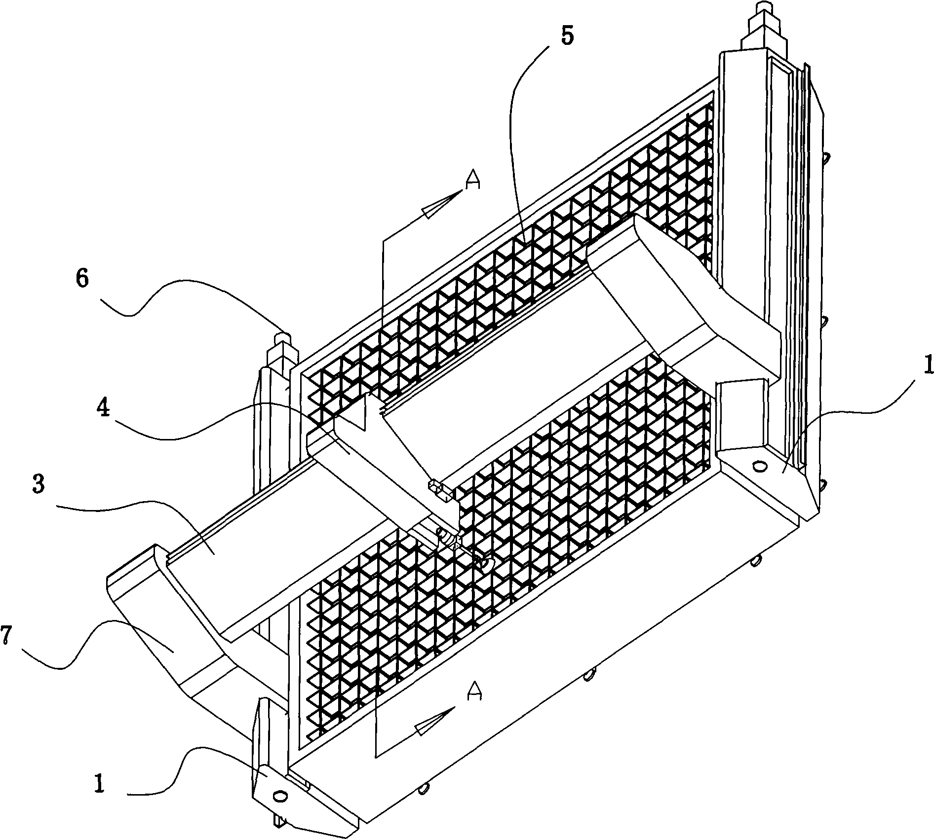
[0009] As shown in the figure, the present invention includes a front and rear mobile frame 1 with a vertical guide rail (ball guide rail), a left and right mobile frame 3 with a horizontal guide rail (ball guide rail) 2 connected to the vertical guide rail, and a left and right mobile device The water jet cutting head 4 on the transverse guide rail 2, the workpiece carrying platform 5 arranged under the water jet cutting head 4, the longitudinal power mechanism 6 that drives the left and right moving frame 3 to move back and forth, and the transverse direction that drives the water jet cutting head 4 to move left and right Power mechanism 7, the transverse guide rail 2 that is arranged on the left and right mobile frame 3 has two covers, is respectively arranged on the upper end 3a of the left and right mobile frame 3 and the front end 3b below, the back s...


PUM


Abstract

The invention relates to a waterjet cutter which is characterized in that the waterjet cutter comprises a front and back moving frame with a vertical guide rail, a left and right moving frame which is connected with the vertical guide rail and is provided with a transverse guide rail, a waterjet cutting head which is arranged on the transverse guide rail in a left and right moving way and a workpiece bearing platform which is arranged under the waterjet cutting head. A support base comprises an inner support base and an external support base. Two ends of the inner support base are wrapping edges for wrapping the back front end and the bottom front end of the left and right moving frame. The external support base comprises a sloping plate and a turned-over edge which is arranged on the two ends of the sloping plate and turns inwards along the wrapping edges on the two ends of the inner support base. A protective cover plate is arranged between the inner support base and the external support base. The protective cover plate comprises a sloping cover plate, a turned-over edge angle plate which is arranged on the upper end of the sloping cover plate and a turned-over edge flat slab which is arranged on the lower end of the sloping cover plate. Compared with the prior art, the waterjet cutter has the advantages that back-washing water and sands during the workpiece processing can be prevented from polluting the guide rails, the swing amplitude of a waterjet cutting spray-head is small so that the mechanical processed workpiece precision cannot be influenced.

Description

Technical field: [0001] The invention relates to a stone or ceramic tile processing device. Background technique: [0002] Existing water jet cutting machines are generally composed of a front and rear moving frame with a vertical ball guide rail, a left and right moving frame with a horizontal ball guide rail connected to the vertical ball guide rail, and a left and right movement set on the horizontal ball guide rail. The waterjet cutting head is composed of a workpiece carrier set under the waterjet cutting head. In order to prevent the horizontal ball guide rail on the left and right moving frame above the workpiece carrier from being polluted by splashed water and sand during workpiece processing, the water The horizontal ball guide rail connected to the knife cutting head is set on the top of the left and right moving frame. Although such a setting can effectively prevent the horizontal ball guide rail on the left and right moving frame located above the workpiece carr...

Claims


Application Information

Patent Timeline
Patent Type & Authority Applications(China)
IPC IPC(8): B24C3/02B24C3/32
Inventor 刘永钦
Owner 刘永钦
Why Eureka
Try Eureka