Shape memory spring driven hinder margin camber variable wing

A memory spring and trailing edge technology, applied in the field of variable trailing edge camber wings, can solve the problems of low aerodynamic efficiency, early air separation, complex mechanism, etc., and achieve the effects of simple structure, improved lift coefficient, and improved economy.

Inactive Publication Date: 2009-08-12
HARBIN INST OF TECH
View PDF0 Cites 26 Cited by
  • Summary
  • Abstract
  • Description
  • Claims
  • Application Information

AI Technical Summary

Problems solved by technology

[0003] The purpose of the present invention is to provide a variable trailing edge camber wing driven by a shape memory spring, which replaces the traditional mechanical drive mechanism, so as to solve the problems of complex and heavy control surface mechanism of the existing aircraft, premature airflow separation and low aerodynamic efficiency. question

Method used


Image

  • Shape memory spring driven hinder margin camber variable wing
  • Shape memory spring driven hinder margin camber variable wing

Examples


specific Embodiment approach 1

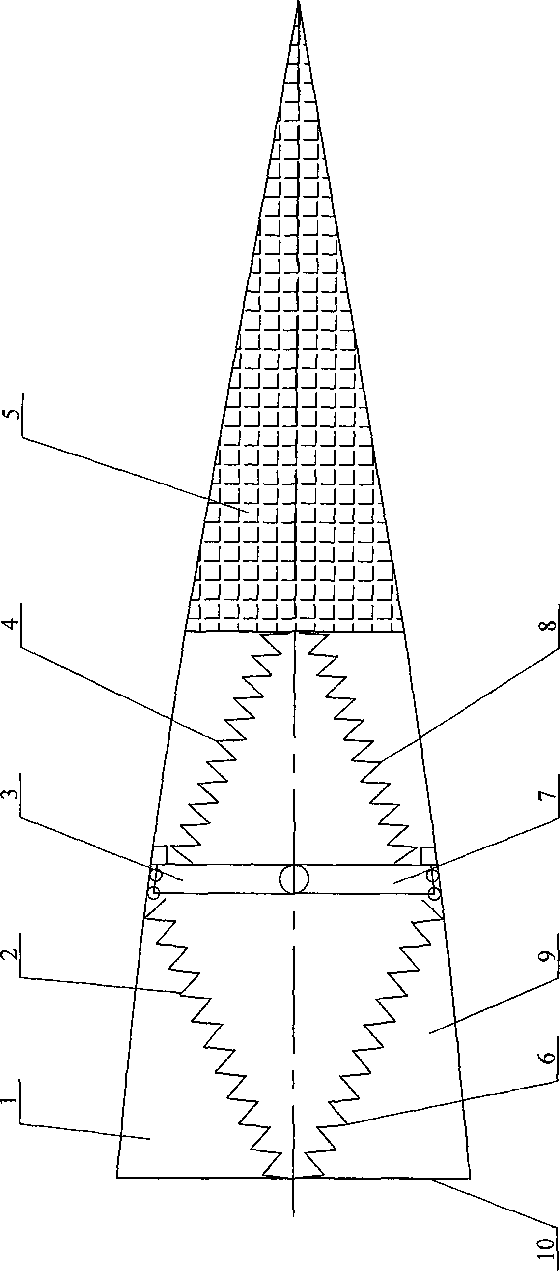
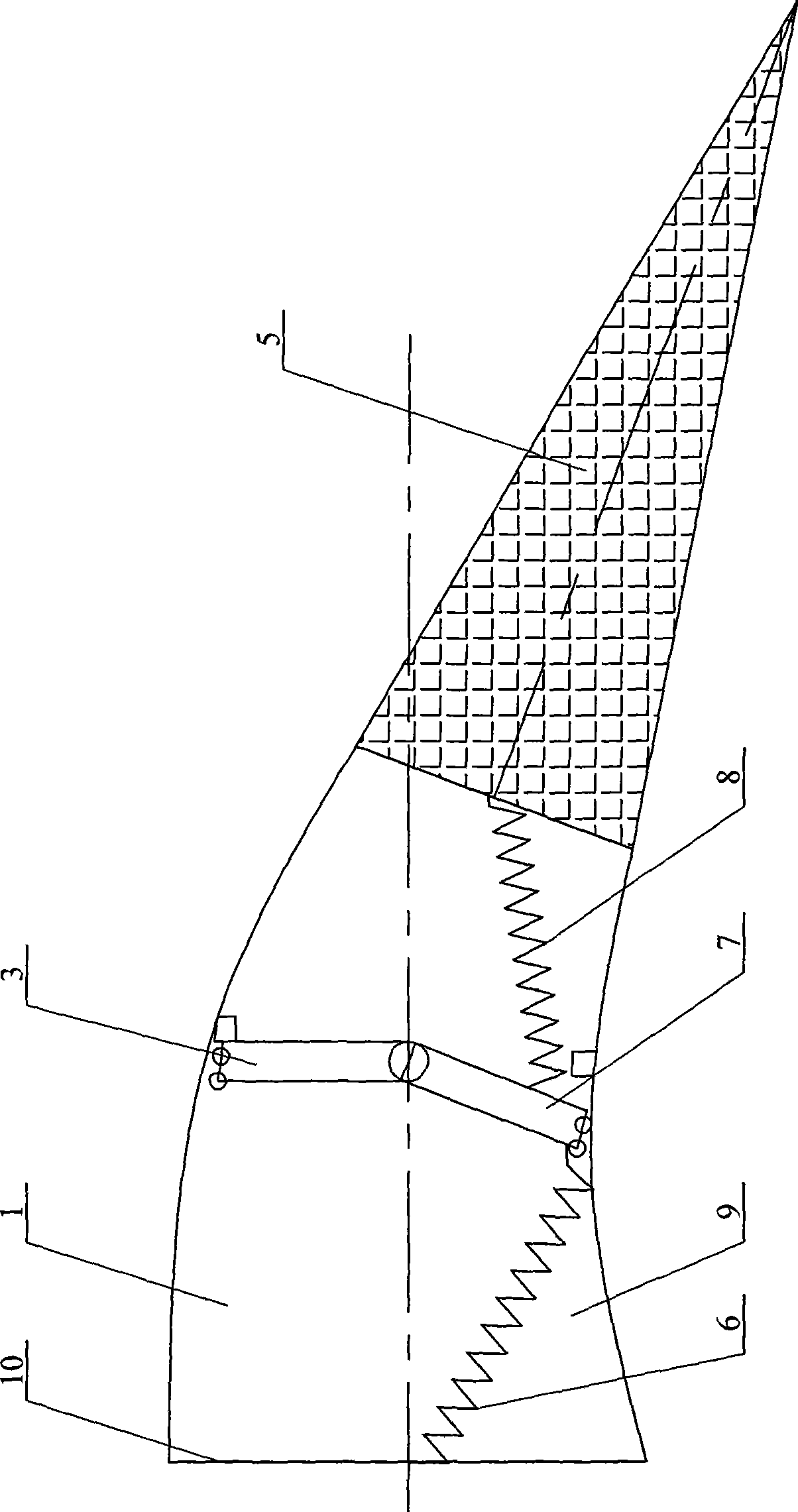
[0007] Specific implementation mode one: combine figure 1 Describe this embodiment, the variable trailing edge camber airfoil of this embodiment includes the wing trailing edge 5; The variable trailing edge camber airfoil also includes an upper metal sheet 1, a first shape memory spring 2, an upper strut 3, The second shape memory spring 4, the third shape memory spring 6, the lower pillar 7, the fourth shape memory spring 8, the lower metal sheet 9 and the connection plate 10; the front end surface of the upper metal sheet 1 is fixed to the upper end of the connection plate 10 connection, the rear end surface of the upper sheet metal 1 is fixedly connected to the upper end of the front end surface of the wing trailing edge 5, the front end surface of the lower sheet metal 9 is fixedly connected to the lower end of the connecting plate 10, and the rear end surface of the lower sheet metal 9 is connected to the machine. The lower end of the front end of the wing trailing edge 5...

specific Embodiment approach 2

[0008] Specific implementation mode two: combination figure 1 This embodiment is described. The difference between this embodiment and the first embodiment is that the two ends of the first shape memory spring 2 of this embodiment are respectively fixedly connected to the middle part of the plate 10 and the middle part of the upper thin metal plate 1. The two ends of the second shape memory spring 4 are fixedly connected with the upper end of the upper pillar 3 and the middle part of the front end surface of the wing trailing edge 5 respectively, and the two ends of the third shape memory spring 6 are connected with the middle part and the lower metal of the fixed plate 10 respectively. The middle part of the thin plate 9 is fixedly connected, and the two ends of the fourth shape memory spring 8 are respectively fixedly connected with the lower end of the lower strut 7 and the middle part of the front end surface of the wing trailing edge 5 . Such setting can make the camber o...

specific Embodiment approach 3

[0009] Specific implementation mode three: combination figure 1 Describe this embodiment, the first shape memory spring 2 of this embodiment, the second shape memory spring 4, the third shape memory spring 6 and the material of the fourth shape memory spring 8 are all TiNi shape memory alloys, have better shape memory effect. Others are the same as in the first or second embodiment.


PUM


Abstract

The invention provides a wing with changeable trailing edge camber driven by a shape memory spring, relating to a wing with a changeable trailing edge camber, and aiming at the problems of traditional airplanes that a mechanism is complex and heavy, airflow breakaway is quite early and aerodynamic efficiency is low. The front end face and the back end face of an upper metal plate are fixedly connected with the front end faces of a connecting plate and the trailing edge; the front end face and the back end face of the lower metal plate are fixedly connected with the front end face of the connecting plate and the trailing edge; the same side surface of the upper metal plate and the lower metal plate are fixed with an upper prop stay and a lower prop stay; the two ends of a first shape memory spring are fixedly connected with a fixed plate and the upper metal plate; the two ends of a second shape memory spring are fixedly connected with the front end faces of the upper prop stay and the trailing edge; the two ends of a third shape memory spring are fixedly connected with the fixed plate and the lower metal plate; and the two ends of a fourth shape memory spring are fixedly connected with the front end faces of the lower prop stay and the trailing edge. The invention has the advantages of light weight, simple structure and high aerodynamic efficiency.

Description

technical field [0001] The invention relates to a variable trailing edge camber wing. Background technique [0002] At present, the control surfaces (such as ailerons and flaps) of most aircraft use mechanical drive mechanisms to change the camber of the wings to provide the aircraft with the aerodynamic force required for maneuvering. However, the control surface using a mechanical drive mechanism has the problems of complex mechanism, heavy weight, premature separation of airflow, and low aerodynamic efficiency. Contents of the invention [0003] The purpose of the present invention is to provide a variable trailing edge camber wing driven by a shape memory spring, which replaces the traditional mechanical drive mechanism, so as to solve the problems of complex and heavy control surface mechanism of the existing aircraft, premature airflow separation and low aerodynamic efficiency. question. [0004] The technical scheme that the present invention takes for solving the...

Claims


Application Information

Patent Timeline
Patent Type & Authority Applications(China)
IPC IPC(8): B64C3/44B64C3/50
Inventor 尹维龙陈以金刘力博冷劲松
Owner HARBIN INST OF TECH
Why Eureka
Try Eureka