Vapor-liquid separation method for vertical condenser and condenser

A technology of vapor-liquid separation and condenser, which is applied in steam/steam condensers, heat exchanger shells, lighting and heating equipment, etc. It can solve the limitation of condensate flow range, insufficient suction force, and affect the effect of liquid separation, etc. problem, to achieve the effect of ingenious structural design and guaranteed steam resistance

Inactive Publication Date: 2012-05-23
TSINGHUA UNIV
View PDF2 Cites 2 Cited by
  • Summary
  • Abstract
  • Description
  • Claims
  • Application Information

AI Technical Summary

Problems solved by technology

[0004] The header 200 in the above two patents both uses a single drain pipe 201 as a leaking liquid vapor blocking device. Leakage, but this structure brings the following problems: first, the diameter of the drain pipe 201 is smaller than that of the header 200, the flow range of the condensate is greatly restricted, and sometimes there is a problem of poor drainage
Although in the latter patent a liquid dispensing device (such as Figure 4 shown), but since the upper surface of the liquid separation device adopts a solid top cover 202, the contact surface between the condensate and the liquid separation device is the side surface of the porous medium during the operation of the condenser, so the liquid separation driving force of the liquid separation device is mainly the porous core 203 Capillary suction force, and the size of the suction force is determined by the structural parameters of the selected porous medium, and the self-adjusting ability is weak. When the amount of condensate is large, there may be a problem of insufficient suction force, which affects the separation. In addition, the structure of the liquid separation device is relatively complicated, and large-scale production and subsequent installation work in industrial production will bring certain difficulties

Method used


Image

  • Vapor-liquid separation method for vertical condenser and condenser
  • Vapor-liquid separation method for vertical condenser and condenser
  • Vapor-liquid separation method for vertical condenser and condenser

Examples


Embodiment 1

[0042] Embodiment 1: A kind of vertical tube condenser unit in series

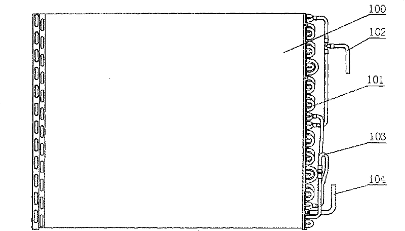
[0043] As shown in Figure 5, this embodiment includes a heat exchange unit module A, the heat exchange unit module A includes a plurality of sets of heat exchange tubes 1 arranged vertically in descending order from top to bottom (or from bottom to top), the heat exchange tubes 1 is provided with fins 11 outside. Each group of heat exchange tubes 1 is connected through multi-stage headers 2 installed at both ends, and the number of stages of heat exchange tubes 1 and headers 2 can be adjusted as required. A steam inlet 21 is arranged on the first cascade box 2 (the uppermost header in the figure, but not limited to this). The first cascade box 2 communicates with the second cascade box 2 through the first group of heat exchange tubes 1, and the second cascade box 2 communicates with the third cascade box 2 through the second group of heat exchange tubes 1, ... until finally First header 2. Each set of h...

Embodiment 2

[0046] The leaking liquid vapor arresting device 3 in this embodiment includes a base plate 31 having the same cross-sectional size as the liquid collecting guide pipe 2, and the center of the base plate 31 has a main hole 32 with an equivalent diameter of 2 to 5 mm and the same aperture, surrounding the main hole 32 is evenly arranged with a circle of auxiliary holes 33 with an equivalent diameter less than 2 mm and the same equivalent aperture. When the condensate produced in the heat exchange tube 1 upstream of the condenser is less, the liquid separated from the header 2 will form a layer of liquid film on the surface of the main hole 32 and the auxiliary hole 33 of the substrate 31, preventing liquid and gas from flowing The main orifice 32 and the auxiliary orifice 33 flow out. When the liquid volume increases slightly, the main hole 32 with a larger aperture will seep first, which is equivalent to the single drain pipe in the prior art. When the amount of separated liq...

Embodiment 3

[0048] Such as Figure 8 , Figure 9 As shown, the size ranges of the main hole 32 and the auxiliary hole 33 in this embodiment are similar to that of Embodiment 1, the difference is that the main hole 32 and the auxiliary hole 33 are frustum holes with variable equivalent apertures, and the equivalent apertures can be larger at the top and lower at the bottom. Small; it can also be small at the top and large at the bottom, and it can also be in any form of variable cross-sectional area. This structure enables both the main hole 32 and the auxiliary hole 33 to carry a certain amount of condensate. When the amount of condensate is relatively low, the main hole 32 can also ensure continuous drainage and prevent steam from passing through. The presence of condensate in the pores of the auxiliary holes 33 can improve its steam resistance ability and prevent steam from passing through, and can also improve the steam resistance ability and accelerate liquid discharge according to t...


PUM


Abstract

The invention relates to a vapor-liquid separation method for a vertical condenser and a condenser. The vapor-liquid separation method comprises that: 1) multilevel headers are arranged at two ends of a plurality of groups of heat exchange tubes which are in vertical descending arrangement, liquid collecting and flow guiding tubes communicated with the headers are all provided with a liquid leaking and vapor stopping device inside to make the liquid collecting and flow guiding tubes form an independent liquid separation space, and the liquid leaking and vapor stopping device is provided with at least one equivalent main hole and a plurality of equivalent auxiliary holes; 2) vapor enters the plurality of groups of heat exchange tubes in turn for condensation, condensate liquid flows into the liquid collecting and flow guiding tubes, and when accumulated liquid in the liquid separation space is less, liquid films formed on the tops of the main hole and the auxiliary holes can prevent the vapor from leaking from the liquid collecting and flow guiding tubes; 3) when the accumulated liquid is more, the accumulated liquid firstly penetrates the main hole to flow out, and the auxiliary holes are sealed by the liquid films formed on the tops continuously; and 4) when the thickness of an accumulated liquid layer is increased, the accumulated liquid gradually penetrates the auxiliary holes and flows out from the main hole and the auxiliary holes simultaneously. The condenser adopts the vapor-liquid separation method and the liquid leaking and vapor stopping device. The method effectively solves the problem that the liquid discharge amount of the condenser is restricted in the prior art.

Description

technical field [0001] The invention relates to a condenser, in particular to a vapor-liquid separation method of a vertical condenser and the condenser. Background technique [0002] A traditional air-cooled vapor-liquid phase change condenser includes a shell 100, a heat exchange tube 101, a steam inlet 102, a tee pipe 103 and a condensate outlet 104 (such as figure 1 As shown), wherein the heat exchange tube 101 is usually a serpentine tube, relying on air convection heat exchange outside the heat exchange tube 101 to condense the steam in the heat exchange tube 101. In the process of condensation heat transfer, as the condensation progresses, the condensate on the wall gradually increases, and then the film formation hinders the contact between the steam and the wall, which is the main thermal resistance of the condensation heat transfer. During the condensation process, the liquid film gradually thickens, and in the long-term later, it will be a complex two-phase flow ...

Claims


Application Information

Patent Timeline
Patent Type & Authority Patents(China)
IPC IPC(8): F28B1/06F28F9/02F28F9/22
Inventor 彭晓峰王珍陆规吴迪张易阳
Owner TSINGHUA UNIV
Why Eureka
Try Eureka