Electronic timepiece with internal antenna

An electronic clock, built-in technology, used in clocks, antenna supports/installation devices, electronic timers, etc., can solve the problems of easy breakage, enlargement, and large-scale watches of amorphous films, and achieves easy antenna tuning frequency. Effect

Inactive Publication Date: 2009-08-12
SEIKO EPSON CORP
View PDF2 Cites 13 Cited by
  • Summary
  • Abstract
  • Description
  • Claims
  • Application Information

AI Technical Summary

Problems solved by technology

[0007] However, in the conventional structure in which end caps are attached to both ends of the laminated core of the antenna as described in Patent Document 1, the outer shape of the timepiece module increases by the amount of end caps, making it difficult to reduce the thickness and size of the timepiece. question
[0008] In addition, in the structure in which the amorphous thin film is fixed to the core as described in Patent Document 2, there is a problem that the amorphous thin film is easily broken when an impact is applied to the timepiece.
The breakage of the amorphous thin film can be prevented by providing a structure such as resetting the holding member, but when such a holding member is provided, there is a problem that the size of the watch is increased.

Method used


Image

  • Electronic timepiece with internal antenna
  • Electronic timepiece with internal antenna
  • Electronic timepiece with internal antenna

Examples


no. 1 approach

[0101] Hereinafter, a first embodiment of the present invention will be described based on the drawings.

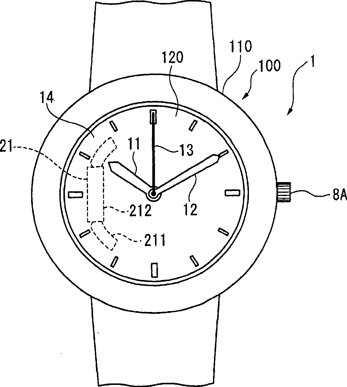
[0102] figure 1 It is a front view of the radio-controlled timepiece as the antenna built-in type electronic timepiece according to the first embodiment of the present invention.

[0103] exist figure 1 Among them, the radio-controlled timepiece 1 is an analog timepiece (analog timepiece) having pointers 11, 12, 13 and a dial 14, and is capable of receiving long-wave standard radio waves as external wireless information with time information and adjusting the hands according to the received time information. 11, 12, 13 A timepiece for correcting the position of the hands.

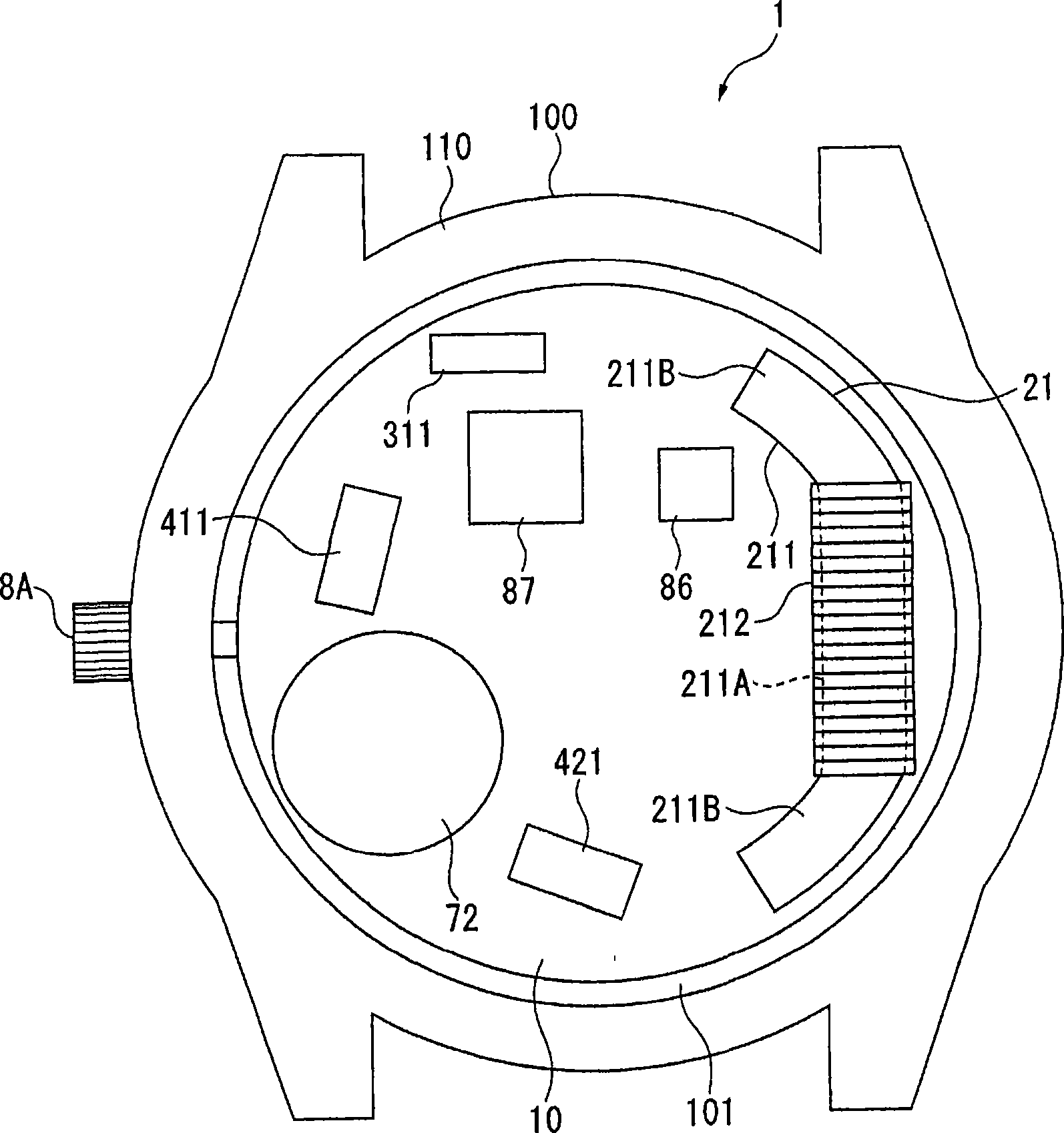
[0104] This radio-controlled timepiece 1 comprises: hands 11, 12, 13, dial 14, module 10 (referring to figure 2 ), and the housing 100 that accommodates these pointers 11, 12, 13, dial 14, module 10, etc. inside.

[0105] Here, the dial 14 is preferably formed of a non-conductive material such as ...

no. 2 approach

[0164] Next, a second embodiment of the present invention will be described with reference to the drawings. In addition, in the following drawings and embodiments, the same structures as those of the radio-controlled timepiece 1 of the above-mentioned first embodiment are given the same reference numerals, and description thereof will be simplified or omitted.

[0165] Figure 9 It is a sectional view showing a section near the guide portion of the antenna in the radio-controlled timepiece of the second embodiment.

[0166] The radio-controlled timepiece 1A of the second embodiment is formed by laminating a plurality of amorphous foil sheets 140 formed on the base plate 102 of the first embodiment.

[0167] That is, on the base plate 102 in the radio-controlled timepiece 1A of the second embodiment, as Figure 9 As shown, a plurality of amorphous foil sheets 140 are stacked at positions not overlapping the coil overlapping region 104 but overlapping the guide overlapping reg...

no. 3 approach

[0175] Next, a third embodiment of the present invention will be described with reference to the drawings. In addition, in the following drawings and embodiments, the same structures as those of the radio-controlled timepiece 1 of the above-mentioned first embodiment are given the same reference numerals, and description thereof will be simplified or omitted.

[0176] Figure 10 It is a sectional view showing a section near the guide portion of the antenna in the radio-controlled timepiece of the third embodiment.

[0177] In the radio-controlled timepiece 1A of the above-mentioned second embodiment, the structure in which the amorphous foil layer 141 formed by laminating the amorphous foil sheets 140 is formed on the dial-facing surface 103 of the base plate 102 is adopted. In the corrected timepiece 1B, the amorphous foil 140 is stacked toward the guide portion 211B side. That is, if Figure 10 As shown, in the guide overlapping area 105 of the bottom plate 102, a communi...


PUM


Abstract

The present invention provides an electronic timepiece with an internal antenna, which can increase the characteristic of antenna without causing the large size of timepiece. An electric wave correcting clock (1) comprises the following components: the antenna which is provided with an elongated magnet core (211) formed by magnet and a coil (212) coiled on the magnetic core (211); a module (10) for containing the antenna (21); and a dial plate (14) which is formed by non-conductive material. Furthermore, an amorphous foil (140) which has a magnetic conductivity larger than that of the dial plate (14) is installed between the dial plate (14) and a module (10) of the electric wave correcting clock (1) in a vertical view for observing the surface orthogonal with the direction from the dial plate (14) to the module (10) at the position that is not overlapped with the coil overlapping area (104) overlapped with the coil winding part (211A) and is overlapped with the guiding overlapping area (105) overlapped with the guiding part (211B).

Description

technical field [0001] The present invention relates to an antenna built-in electronic timepiece capable of receiving external wireless information through an antenna. Background technique [0002] Conventionally, antenna built-in electronic timepieces, such as radio-controlled timepieces, are known, which receive external wireless information including time information from the outside with an antenna and perform processing such as time adjustment. In such electronic timepieces with built-in antennas, in order to improve antenna characteristics, various structures for improving the magnetic concentration effect in the antenna have been studied (for example, refer to Patent Documents 1 and 2). [0003] The wristwatch described in Patent Document 1 employs a built-in antenna including a laminated core, a winding portion for winding a winding wire around the laminated core, and end caps fixed to both ends of the laminated core. [0004] In addition, the wristwatch described i...

Claims


Application Information

Patent Timeline
Patent Type & Authority Applications(China)
IPC IPC(8): G04G1/06G04C9/02H01Q1/24H01Q7/08G04G21/04G04R60/12
Inventor 宫原史明
Owner SEIKO EPSON CORP
Why Eureka
Try Eureka