Intelligent high voltage duplicate power source converting switch
A dual power switching and power switching technology, applied in high voltage/high current switches, electric switches, emergency power supply arrangements, etc., can solve the problems of personnel and equipment damage, line power supply, arc short circuit, air breakdown, etc., to eliminate potential safety hazards, The effect of ensuring safe use and simplifying the structure
- Summary
- Abstract
- Description
- Claims
- Application Information
AI Technical Summary
Problems solved by technology
Method used
Image
Examples
Embodiment 1
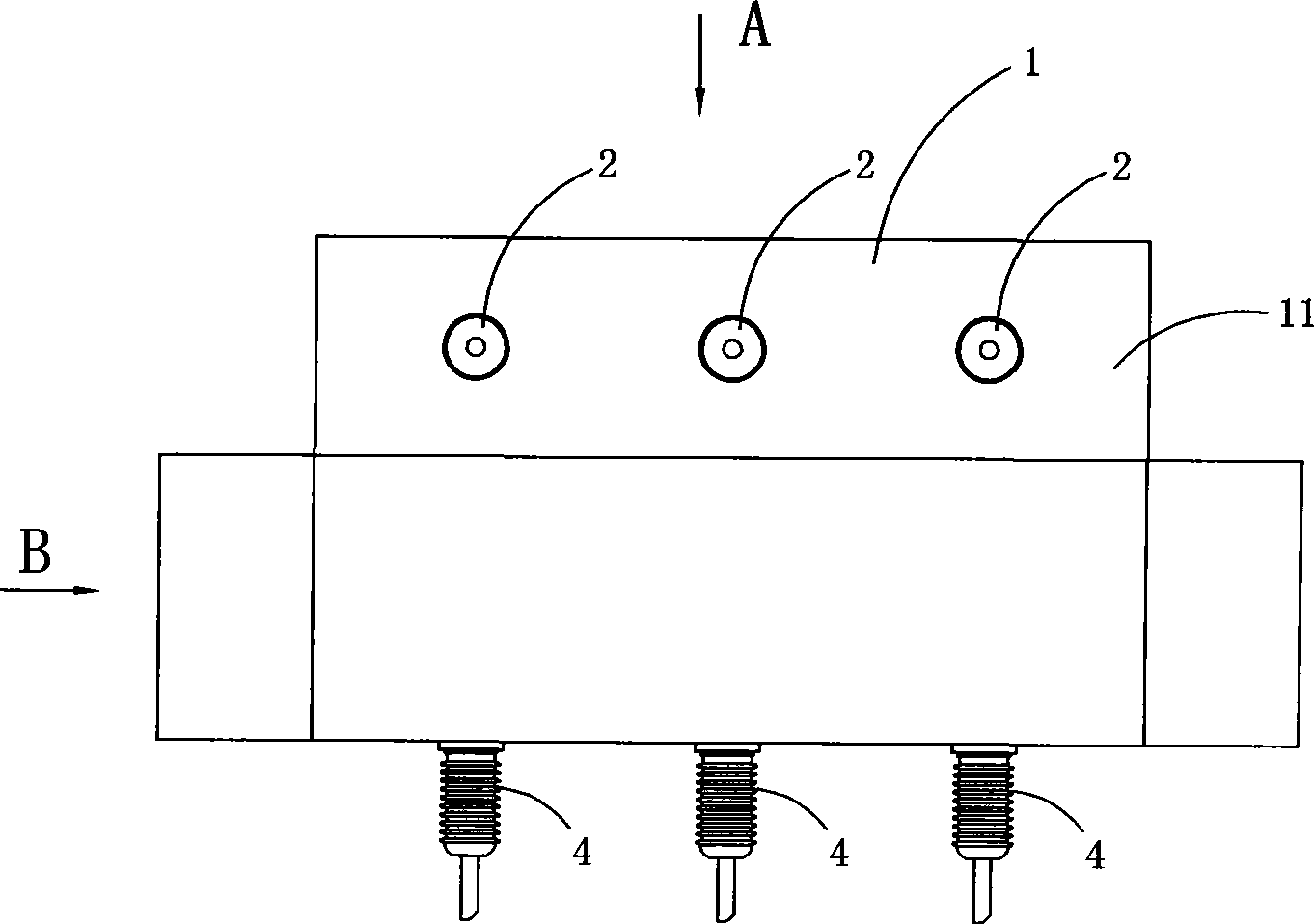
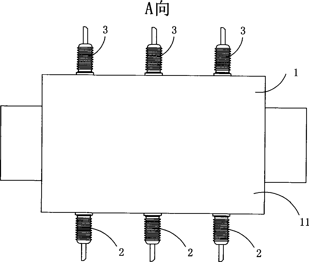
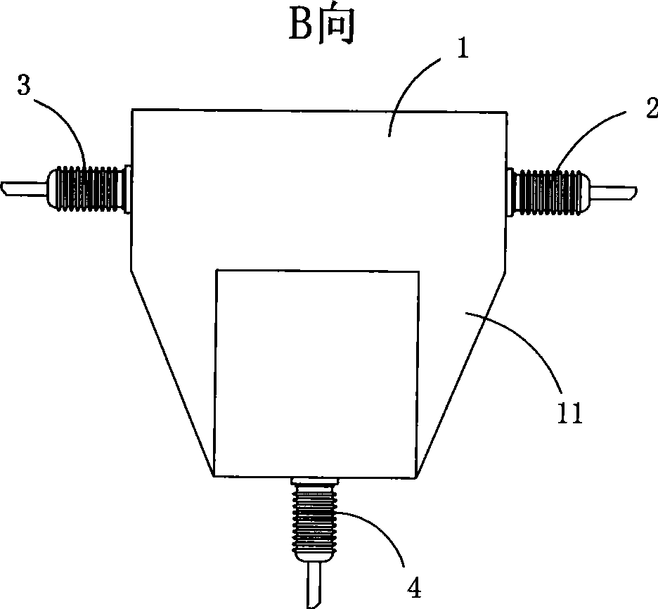
[0027] Figure 1 to Figure 4 A specific embodiment of the invention is shown in which figure 1 It is the front view outline drawing of the first structure of the present invention; figure 2 yes figure 1 The A-direction view of the intelligent high-voltage dual power supply switch shown; image 3 yes figure 1 The B-direction view of the intelligent high-voltage dual power supply switch shown; Figure 4 yes figure 1 The schematic diagram of the structure of the intelligent high-voltage dual power supply switching switch is shown.
[0028] This embodiment is an intelligent high-voltage dual power switch, see figure 1 and Figure 4 , comprising an airtight box 1, three main power terminals 2, three backup power terminals 3 and three load terminals 4 arranged on the airtight box body 11, and a power switch arranged in the airtight box 1 Mechanism 5, and operating mechanism (not drawn on the figure); Described power switching mechanism 5 comprises a switching main shaft 51,...
Embodiment 2
[0031] Figure 5 It is the second structural schematic diagram of the present invention, showing the second specific implementation mode of the present invention.
[0032] This embodiment is basically the same as Embodiment 1, the difference is: see Figure 5 , the switch also includes a three-phase vacuum circuit breaker device 6, the three-phase vacuum circuit breaker device 6 includes three vacuum interrupters 61, three moving contacts 62, three static contacts 63 and an operating mechanism 64 Each of the moving contacts 62 is softly connected to a corresponding switching contact knife 6; the operating mechanism 64 includes a drive shaft 641 and a drive rod 642 for connecting the drive shaft 641 and the moving contact 62; The outer surface of the static contact 63 of each vacuum circuit breaker is provided with an insulating post 631 to form an insulating terminal. The insulating terminal wrapped with the static contact 63 is arranged on the outer surface of the box body 1...
Embodiment 3
[0036] Figure 6 It is the third structural schematic diagram of the present invention, showing the third specific implementation mode of the present invention.
[0037] This embodiment is basically the same as Embodiment 2, the difference is: see Figure 6 , each of the throwing and cutting contact blades 52 is a V-shaped contact blade.
[0038] Embodiment 2 and embodiment 3 have positive advantages: (1) each embodiment reduces a switching main shaft, by The three throwing and cutting contact knives and the mechanical interlocking device of the switching spindle greatly simplify its structure; in addition, even if the products of each embodiment are damaged for some reason, since there is only one set of throwing and cutting contact knives, and at most they can only be connected with one set of power supply The terminals are electrically connected, so there will be no accidents of dual power feeding at the same time, effectively eliminating potential safety hazards. (2) The ...
PUM
 Abstract
Description
Claims
Application Information
 - R&D
- Intellectual Property
- Life Sciences
- Materials
- Tech Scout
- Unparalleled Data Quality
- Higher Quality Content
- 60% Fewer Hallucinations
Browse by: Latest US Patents, China's latest patents, Technical Efficacy Thesaurus, Application Domain, Technology Topic, Popular Technical Reports.
© 2025 PatSnap. All rights reserved.Legal|Privacy policy|Modern Slavery Act Transparency Statement|Sitemap|About US| Contact US: help@patsnap.com


