Humidity control of an electrical device

A technology for electrical equipment and humidity control, which is applied in the direction of electrical equipment shells/cabinets/drawers, electrical components, lighting and heating equipment, etc. It can solve problems such as attachment and entry, and achieve reliable layout without failure or damage.

Inactive Publication Date: 2009-08-12
TELEFON AB LM ERICSSON (PUBL)
View PDF6 Cites 17 Cited by
  • Summary
  • Abstract
  • Description
  • Claims
  • Application Information

AI Technical Summary

Problems solved by technology

Also, if the outlet tube is too small, water may adhere to the inside of the tube due to capillary forces
Conversely, if the tube is too large, moisture in the form of humid air may enter the housing from the outside

Method used


Image

  • Humidity control of an electrical device
  • Humidity control of an electrical device
  • Humidity control of an electrical device

Examples


Embodiment Construction

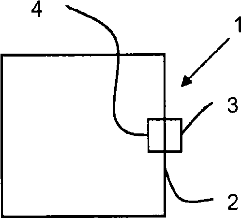
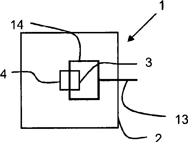
[0050] Hereinafter, different embodiments of the present invention, namely, an apparatus for dehumidifying the interior of a housing including an electric device, will be described with reference to the accompanying drawings. The examples (figures) are intended to illustrate how the different parts of the elements of the dehumidifier, such as the heating and cooling elements, can be mounted in connection with the housing and what are the details of the different configurations of the dehumidifier.

[0051] The general principle in these figures is that solid arrows (when not associated with a reference number) indicate the flow of water or condensed moisture, that is, water in a liquid state; dashed arrows indicate moist air or The flow of fog, that is, the flow of water in a gaseous state.

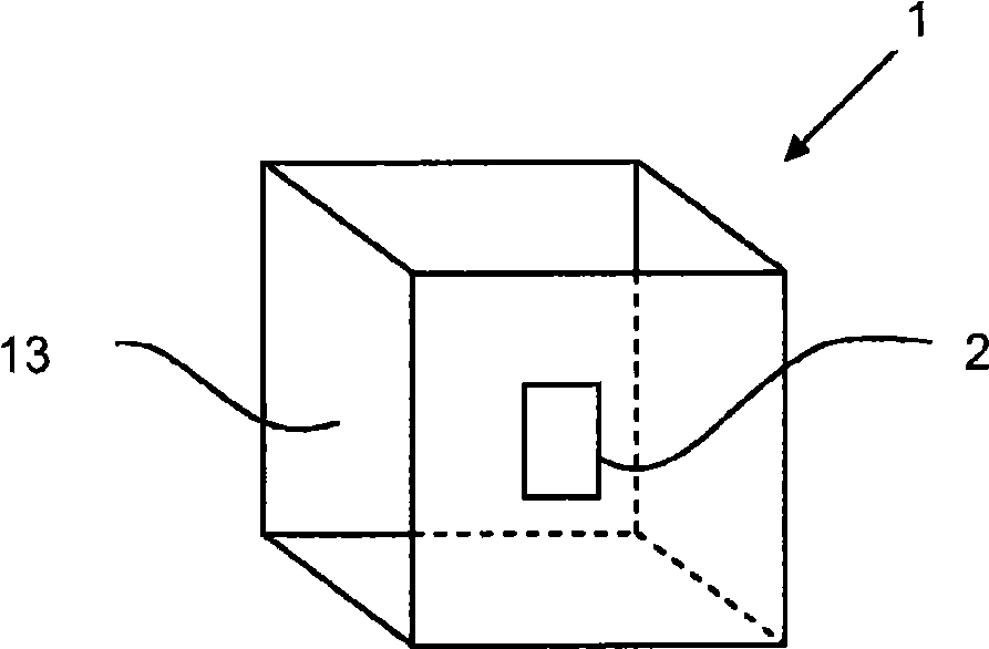
[0052] figure 1 is a simple schematic overview of the intended use of the dehumidifier 2 and shows an enclosure 1 for electrical equipment (not shown) comprising the dehumidifier 2 on th...


PUM


Abstract

The invention relates to a device 2 and a method for dehumidifying and control of humidity inside an enclosure 1 comprising electrical equipment. The device 2 comprises a heating element 3 located to be in contact with the ambient air of the exterior of the enclosure 1 and a cooling element 4 located to be in contact with the ambient air of the interior of the enclosure 1. Dew condensed at the cooling element 4 is guided to the heating element 3 so that humidity from the air, condensed at the cooling element 4, may be transported to the heating element 3 to be vaporised wherein the water guiding means comprises a capillary structure 6. In still another aspect of the invention, the functionality of the heating and cooling elements may be switched so as to reverse the flow of water and provide a humidity control arrangement.

Description

technical field [0001] The present invention relates to apparatus and methods for dehumidifying and controlling humidity inside an enclosure (or enclosure) including electrical equipment. Background technique [0002] Electrical equipment intended to be placed where it may be exposed to moisture or water is usually protected by a waterproof enclosure. However, there may be small inlets, such as gaps, small holes or diffuse leaks, through which water may enter the housing. The complete waterproofing of these housings (cabinets) is usually a costly procedure and in most cases water, eg fog or humid air, may have entered the housings when the product was new. Even if the product is made completely waterproof, due to aging during normal use, accidental impact or severe force applied to the product, or exposure to environments such as the sun, wind and rain, the environment may cause the aging of the waterproof protection system so that water or humid air can enter the case, so...

Claims


Application Information

Patent Timeline
Patent Type & Authority Applications(China)
IPC IPC(8): F24F3/14F24F5/00H05K5/02
CPCF24F3/14H05K5/0213F24F5/0042H05K5/0212
Inventor M·约翰逊T·尼尔森
Owner TELEFON AB LM ERICSSON (PUBL)
Why Eureka
Try Eureka