
Wire laying-off device of heavy-duty drawing machine

A technology of pay-off device and large drawing machine, which is applied in the field of pay-off device, can solve the problems such as the pause of large drawing machine, the large area occupied by the pay-off device, and the influence on the drawing efficiency, so as to reduce the occupied area and labor Strength, the effect of improving wire drawing efficiency

Inactive Publication Date: 2009-08-19
JIANGSU JIACHENG TECH
View PDF6 Cites 15 Cited by
  • Summary
  • Abstract
  • Description
  • Claims
  • Application Information

AI Technical Summary

Problems solved by technology

[0003] 1. The entire pay-off device occupies a large area;
[0004] 2. The noise generated by the wire 3 sliding back and forth on the guide wheel is very loud;
[0005] 3. The pay-off device cannot perceive the occurrence of abnormal conditions, that is, when the wire 3 is messed up and the entire reel 4 is lifted along with the wire 3, the pay-off device has no way of knowing. At this time, if it is not shut down in time, It will cause damage to the pay-off device and related equipment.
Therefore, during the whole pay-off process, the operator must be on duty, staring at the wire rod 3 all the time, and cannot relax for a moment, which greatly increases the labor intensity of the operator;
[0006] 4. Only one wire reel 4 can be placed at a time. When replacing the wire reel 4, it will cause the whole drawing machine to stop for a long time, which will affect the drawing efficiency

Method used


Image

  • Wire laying-off device of heavy-duty drawing machine
  • Wire laying-off device of heavy-duty drawing machine
  • Wire laying-off device of heavy-duty drawing machine

Examples


Embodiment Construction

[0020] Specific embodiments of the present invention will be described in detail below in conjunction with the accompanying drawings.

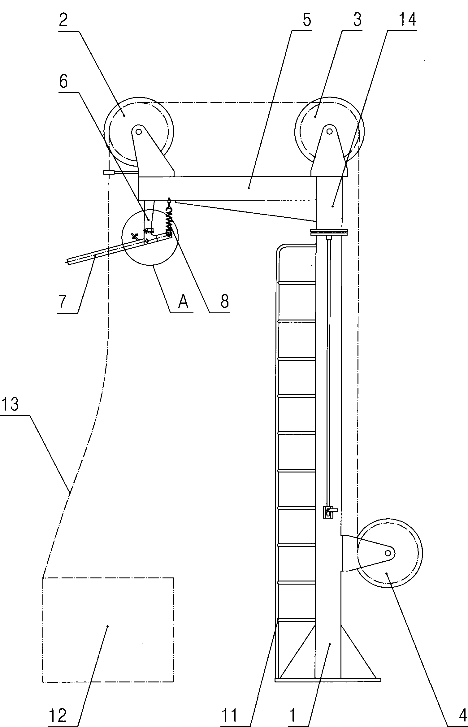
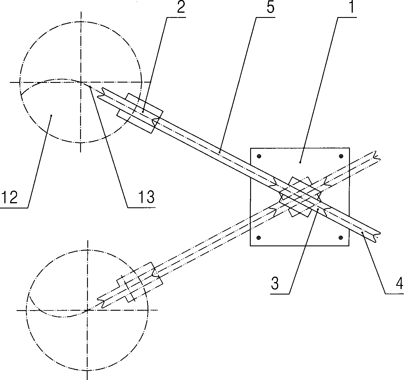
[0021] Such as image 3 As shown, the pay-off device in the large drawing machine of the present invention includes: a pay-off rack 1, a rotating shaft 14 is movable on the top of the pay-off rack 1, a swing arm 5 is provided on the left side of the rotating shaft 14, and a rotating shaft 14 The top is provided with a wire passing wheel 3, and the end of the swing arm 5 is provided with a lead-in wheel 2 matched with the wire-passing wheel 3—the wire-passing grooves on the lead-in wheel 2 and the wire-passing wheel 3 are straight to each other, and the pay-off frame 1 The lower right side of the bottom is provided with the lead-out wheel 4 that cooperates with the thread wheel 3; Figure 5 As shown, the bottom of the swing arm 5 is provided with a hanging arm 6, and the end of the hanging arm 6 is movably provided with a thread-passing plate ...


PUM


Abstract

The invention discloses a pay-off device in a large drawing machine, which has small occupied area and can improve the drawing efficiency. The pay-off device comprises a pay-off stand; the top of the pay-off stand is moveably provided with a rotating shaft; the rotating shaft is provided with a swinging arm; the top of the rotating shaft is provided with a threading wheel; the end part of the swinging arm is provided with a lead-in wheel matched with the threading wheel; and the lower part of the pay-off stand is provided with a lead-out wheel matched with the threading wheel. The pay-off device can be used for the large drawing machine and other drawing devices.

Description

technical field [0001] The invention relates to a wire pay-off device, in particular to a wire pay-off device in a large drawing machine. Background technique [0002] The large drawing machine usually includes five parts: pay-off device, wire drawing device, annealing device, wire storage tension box and wire take-up device. Figure 1, figure 2 As shown, the pay-off device wherein has a structure comprising: a pay-off frame 1 on which a wire pulley 2 is movable. Its function is to straighten out the wire 3 and introduce it into the wire drawing machine. In actual use, this pay-off device has the following disadvantages: [0003] 1. The entire pay-off device occupies a large area; [0004] 2. The noise generated by the wire 3 sliding back and forth on the guide wheel is very loud; [0005] 3. The pay-off device cannot perceive the occurrence of abnormal conditions, that is, when the wire 3 is messed up and the entire reel 4 is lifted along with the wire 3, the pay-off de...

Claims


Application Information

Patent Timeline
IPC IPC(8): B21C47/16B21C47/28
Inventor 钱国平
Owner JIANGSU JIACHENG TECH
Features
  • Generate Ideas
  • Intellectual Property
  • Life Sciences
  • Materials
  • Tech Scout
  • Unparalleled Data Quality
  • Higher Quality Content
  • 60% Fewer Hallucinations
Learn More