Pendulum guide rod type pumping unit

A technology for swinging guide rods and pumping units, which is applied in the direction of production fluid, wellbore/well components, earthwork drilling and production, etc. It can solve the problems of reduced reliability of flexible connecting rods, large peak net torque of the crankshaft, and increased energy consumption, etc. problems, to achieve the effect of improved balance, improved reliability, and large corners

Inactive Publication Date: 2009-08-19
XI'AN PETROLEUM UNIVERSITY
View PDF0 Cites 7 Cited by
  • Summary
  • Abstract
  • Description
  • Claims
  • Application Information

AI Technical Summary

Problems solved by technology

However, the torque factor of the beam pumping unit is too large, resulting in an excessive peak value of the net torque on the crankshaft, excessive fluctuations, and consequently large energy consumption
Therefore, in order to reduce the energy consumption of the beam pumping unit, a lot of technical transformation research has been carried out on the beam pumping unit in recent years, and the double donkey head pumping unit, the downward bias barbell pumping unit, and the curved beam pumping unit have been developed. Beam pumping units, etc., have achieved a certain energy-saving effect, especially the double donkey head pumping unit has the most obvious energy-saving effect. The reliability of the pumping unit is greatly reduced; and, since these types of pumping units are improvements made on the basis of conventional beam pumping units, they have not changed some inherent defects of the original pumping units

Method used


Image

  • Pendulum guide rod type pumping unit
  • Pendulum guide rod type pumping unit
  • Pendulum guide rod type pumping unit

Examples


Embodiment 1

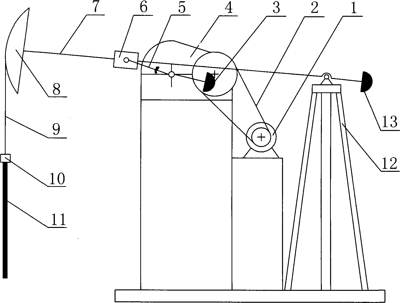
[0021] Such as figure 1 As shown, the present invention comprises electric motor 1, belt transmission mechanism 2, speed reducer 4, crank 5, frame 12, fork 7, donkey head 8, steel rope 9 and sucker rod 11, wherein, the output shaft of electric motor 1 and The input shaft of the belt transmission mechanism 2 is connected through the connection key, the output shaft of the belt transmission mechanism 2 is connected with the input shaft of the reducer 4 through the connection key, and the crank 5 is installed on the output shaft of the reducer 4 through the connection key. Driven by the output shaft of the speed reducer 4, it rotates synchronously with the output shaft of the speed reducer 4. Wherein, the speed reducer 4 is a two-stage gear reduction box.

[0022] The slider 6 is installed on the front end of the crank 5 through the pin shaft, and the rear end of the crank 5 protrudes outside the output shaft of the reducer 4, that is, the reducer 4 is connected to the middle pa...

Embodiment 2

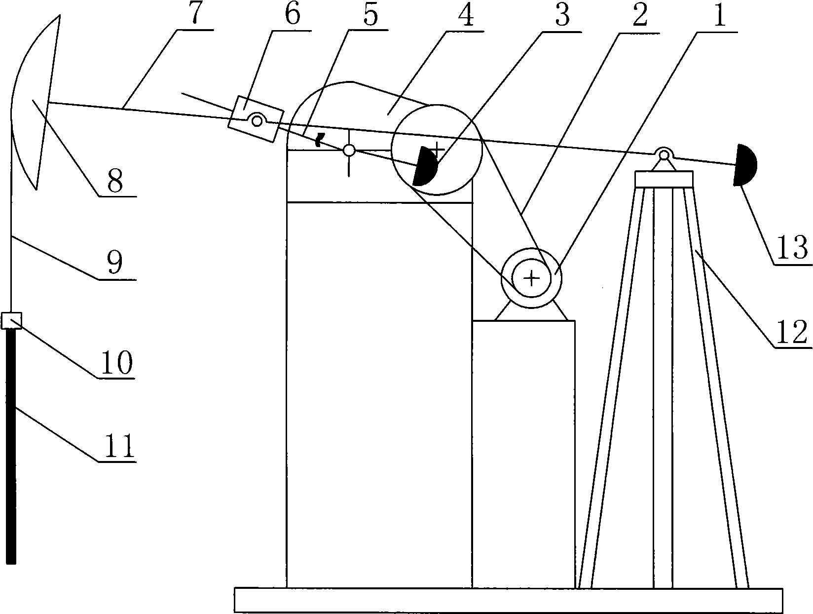
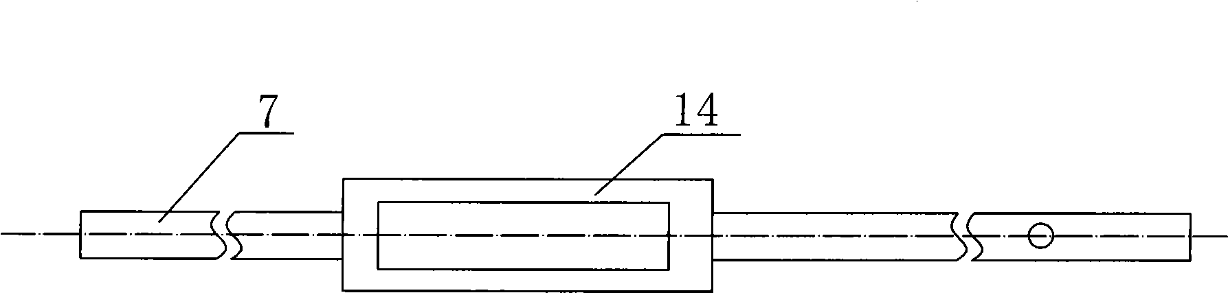
[0026] Such as figure 2 and Figure 4 As shown, the difference between this embodiment and Embodiment 1 is that a slider 6 is fixedly installed on the front part of the swing rod 7 through a pin shaft, and a guide rail 14 is fixedly installed on the front part of the crank 5, and the slider 6 is arranged on the guide rail. 14 miles and slide along the guide rail 14. In this way, during the rotation of the crank 5, through the sliding of the slider 6 on the guide rail 14, the crank 5 drives the swing bar 7 to swing up and down with the frame 12 as the fulcrum, and at the same time, the donkey head 8 on the swing bar 7 Drive the sucker rod 11 to reciprocate up and down.


PUM


Abstract

The invention discloses an oscillating guide bar type oil extractor, comprising a stander, an electric motor, a belt gear, a speed reducer and a crank shaft installed on a reducer output shaft; wherein, an oscillating bar is movably installed on the stander; a horsehead is installed at the front end of the oscillating bar; the lower end of the horsehead is connected with a rope-bar connector; a sucker rod is installed on the rope-bar connector; a slide block is installed on the crank shaft and a guide rail used for the slide block to slide is installed on the oscillating bar; or the slide block is installed on the oscillating bar and the guide rail used for the slide block to slide is installed on the crank shaft; the crank shaft slides on the guide rail by virtue of the slide block and drives the oscillating bar to oscillate up and down with the stander as the fulcrum; the oscillating bar drives the sucker rod to reciprocate up and down by the horsehead, a wire cable and the rope bar. The oil extractor is compact in structure, safe and reliable in working, good in balance and evident in energy-saving effect.

Description

technical field [0001] The invention belongs to the field of oil exploitation equipment, in particular to a swing guide rod type oil pumping unit. Background technique [0002] At present, the mechanical oil extraction equipment in domestic and foreign oilfield oil production projects has a variety of structures, among which the beam pumping unit is the most commonly used, because the beam pumping unit has simple structure, reliable use, convenient operation and maintenance and It can operate reliably and safely for a long time in the harsh natural environment. More than 90% of oil production equipment in my country's oilfields uses beam pumping units. However, the torque factor of the beam pumping unit is too large, resulting in an excessive peak value of the net torque on the crankshaft, excessive fluctuations, and consequently large energy consumption. Therefore, in order to reduce the energy consumption of the beam pumping unit, a lot of technical transformation resear...

Claims


Application Information

Patent Timeline
Patent Type & Authority Applications(China)
IPC IPC(8): E21B43/00
Inventor 任涛
Owner XI'AN PETROLEUM UNIVERSITY
Why Eureka
Try Eureka