Multifunctional sludge formation slitting machine

A technology of sludge forming and strip cutting machine, which is applied in the direction of material forming presses, presses, manufacturing tools, etc., which can solve the problems of low production efficiency and limited application range, and achieve the effect of improving efficiency and expanding application range

Pending Publication Date: 2018-10-19
DALIAN HUANZI TECH
View PDF0 Cites 1 Cited by
  • Summary
  • Abstract
  • Description
  • Claims
  • Application Information

AI Technical Summary

Problems solved by technology

[0002] At present, the sludge drying market has higher and higher requirements on the shape of sludge before entering the dryer. There are strips, granules, and cakes. The existing strip cutter can only make one type of shape. Sludge, low production efficiency, limited application range

Method used


Image

  • Multifunctional sludge formation slitting machine
  • Multifunctional sludge formation slitting machine

Examples


Embodiment 1

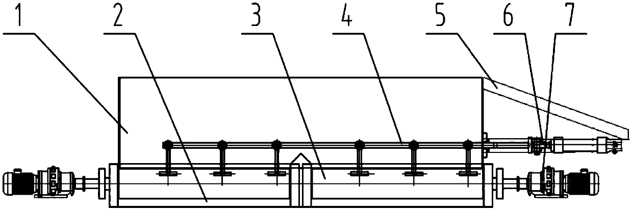
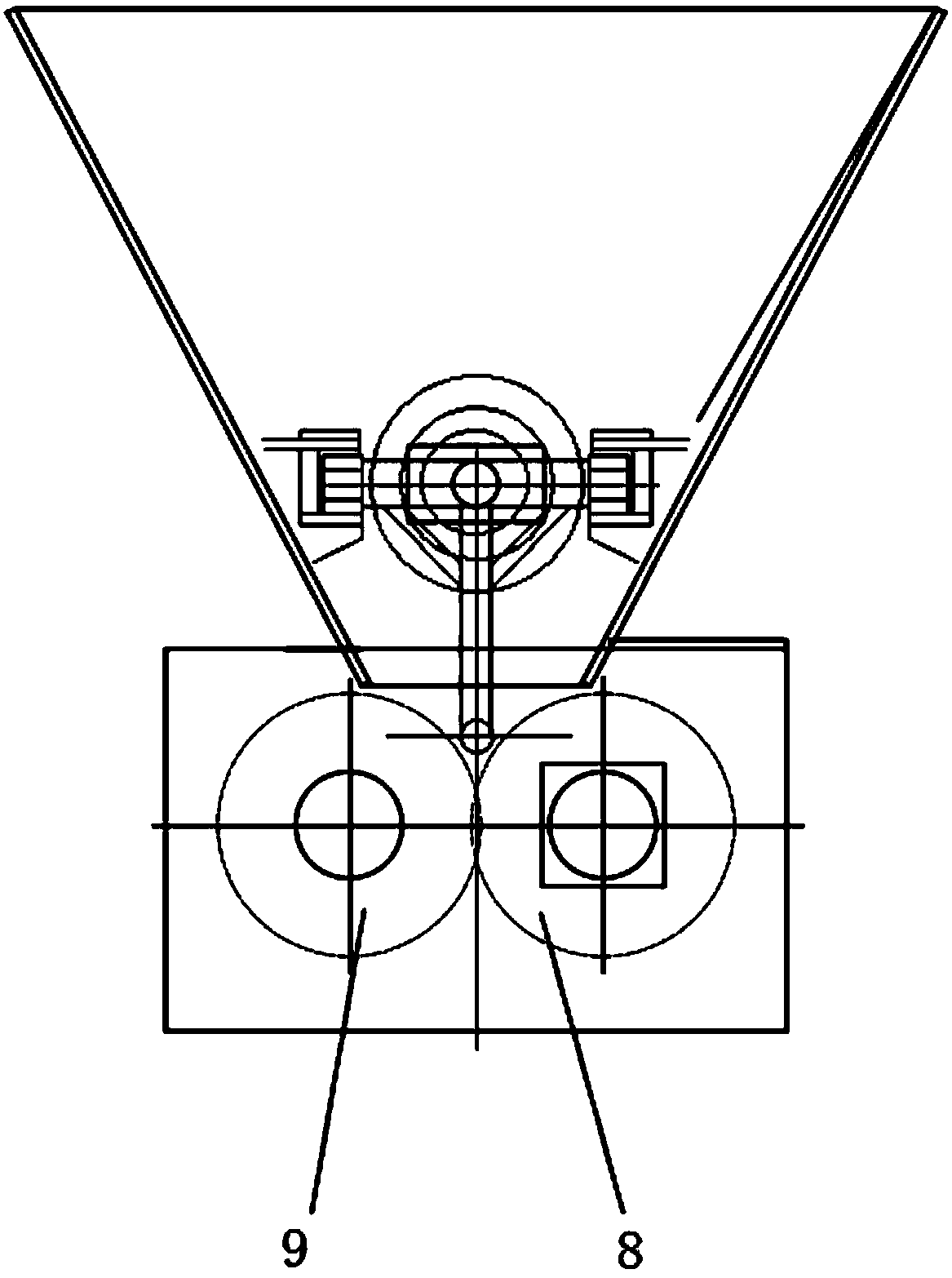
[0016] like figure 1 As shown, a multi-purpose sludge forming and cutting machine can process three types of sludge: municipal sludge, chemical sludge, and electroplating sludge. The forming cavity 2 is connected to the feeding device 1, and the forming cavity 2 is used as a supporting structure and an operating space. There is a forming nip roller 3 inside it. The forming nip roller 3 is composed of two groups, and each group is passed by a driving wheel 8 and a driven wheel 9. The gears are occluded and connected side by side. The forming nip roller 3 is connected to the electrical control device 7 used to make it rotate and control its number of revolutions. The upper part of the forming nip roller 3 is connected to the telescopic device 4. The drooping flat scraper on the top drives the drooping flat scraper to reciprocate through the telescopic rod, thereby offsetting the viscosity of the material, so that the material can be supplied continuously. connect.

[0017] The...

Embodiment 2

[0026] This embodiment is the application of the present invention in a heat pump drying system with a water content of chemical sludge from 65% to 25% and a treatment rate of 80 tons per day. The structure of each part of the device and the connection relationship are all the same as in Embodiment 1, and the difference is:

[0027] The driven wheel rotates at a speed of 40 rad / min. The bite groove of the forming nip roller is a strip block with a size of 10*10mm and a thickness of 8mm. The frequency of the telescopic device is 25 times / min. It is between 0 and 100mm. The fixing device is composed of Q235-B steel and plate, the steel is 40 channel steel, and the thickness of the plate is 10mm. Its parameters are selected within the design range and designed to ensure that the working conditions are met.

Embodiment 3

[0029] This example is the application of the present invention in a heat pump drying system where the water content of electroplating sludge is treated from 75% to 20%, and the treatment rate is 30 tons per day. The structure of each part of the device and the connection relationship are all the same as in Embodiment 1, and the difference is:

[0030] The driven wheel rotates at a speed of 30 rad / min. The nip groove of the forming nip roller is cake-shaped, with a diameter of 12 mm and a thickness of 6 mm. The frequency of the telescopic device is 20 times / min, and the telescopic range is between 0 and 50 mm. , The fixing device is composed of Q235-B shaped steel and plate, the shaped steel is 40 channel steel, and the thickness of the plate is 8mm. Its parameters are selected within the design range and designed to ensure that the working conditions are met.


PUM


Abstract

The invention discloses a multifunctional sludge formation slitting machine and relates to the field of sludge drying. The upper portion of a forming cavity is connected with a feeding device. The forming cavity serves as a supporting structure and a running space and is internally provided with two sets of forming engagement rollers. Each set of forming engagement roller is formed by connecting adrive wheel and a driven wheel side by side in a gear-engaged mode. The forming engagement rollers are connected with electrical control devices used for enabling the forming engagement rollers to rotate and controlling the rotation number of the forming engagement rollers. The upper portions of the forming engagement rollers are connected with a telescopic device, and the telescopic device comprises a telescopic rod and drooping flat scrapers evenly connected to the telescopic rod. The telescopic rod drives the drooping flat scrapers to move back and forth, so that viscosity of materials isoffset, the materials can be supplied continuously, the telescopic rod is connected with a cylinder device, and the cylinder device is connected with the forming cavity through a fixing device. According to the multifunctional sludge formation slitting machine, required shapes before sludge enters a drying machine are met, the drying efficiency is greatly improved, meanwhile, sludge of different types can be processed correspondingly through the identical drying machine, and the application range is extended.

Description

technical field [0001] The invention relates to the field of sludge drying, in particular to a multipurpose sludge forming and cutting machine. Background technique [0002] At present, the sludge drying market has higher and higher requirements on the shape of sludge before entering the dryer. There are strips, granules, and cakes. The existing strip cutter can only make one type of shape. Sludge, low production efficiency, limited application range. SUMMARY OF THE INVENTION [0003] In order to solve the above problems, the present invention provides a multi-purpose sludge forming and cutting machine, and at the same time, the same dryer can also handle different types of sludge accordingly. [0004] The technical solution adopted by the present invention to achieve the above object is: a multi-purpose sludge forming and cutting machine, which is characterized in that: the feeding device is connected above the forming cavity, and the forming cavity is used as a supporti...

Claims


Application Information

Patent Timeline
Patent Type & Authority Applications(China)
IPC IPC(8): B30B11/16B30B15/30
CPCB30B11/16B30B11/165B30B15/30
Inventor 张赜王洪宇徐守宇邓海燕
Owner DALIAN HUANZI TECH
Why Eureka
Try Eureka