
Noncircular stator inner loop curve single-action vane pump

An in-stator, vane pump technology, applied in the field of hydraulic pumps, can solve problems such as limiting the lower limit of the use speed of the vane pump.

Inactive Publication Date: 2009-08-19
王志标
View PDF0 Cites 2 Cited by
  • Summary
  • Abstract
  • Description
  • Claims
  • Application Information

AI Technical Summary

Problems solved by technology

[0003] The purpose of the non-circular stator inner ring curve single-acting vane pump of the present invention is to solve the defect that the vane of the existing vane hydraulic pump closely fits the inner surface of the stator, which is guaranteed by the centrifugal force when the vane rotates, and limits the lower limit of the operating speed of the vane pump, thereby disclosing The technical scheme of the vane pump using a non-circular closed curve as the inner ring curve of the vane pump stator

Method used


Image

  • Noncircular stator inner loop curve single-action vane pump
  • Noncircular stator inner loop curve single-action vane pump
  • Noncircular stator inner loop curve single-action vane pump

Examples


Embodiment approach 1

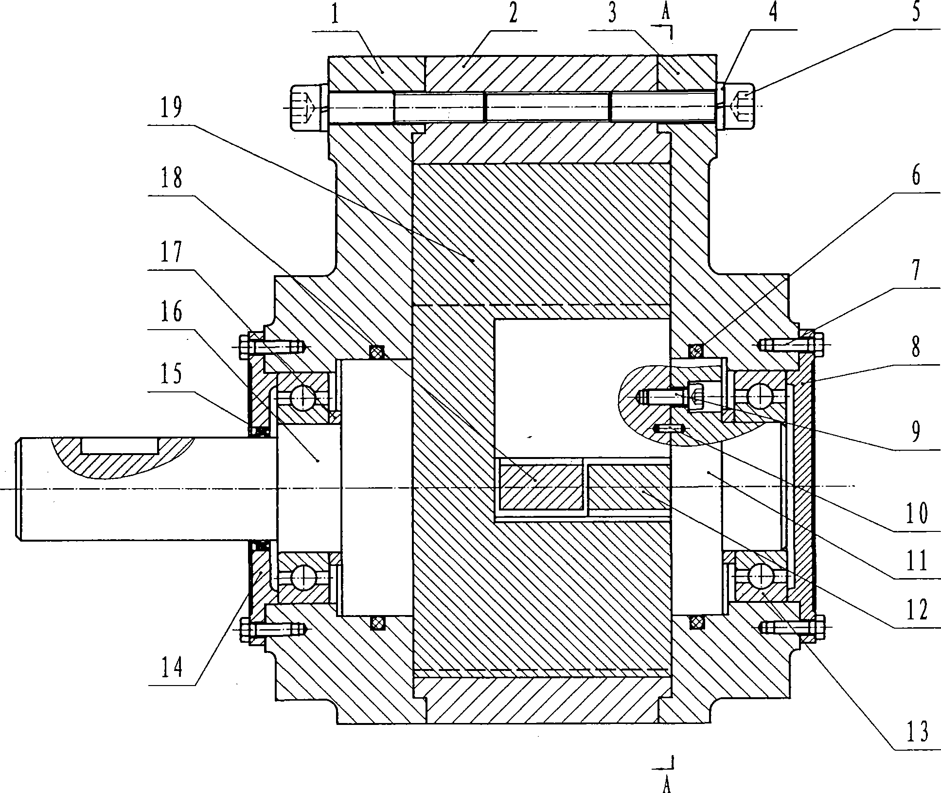
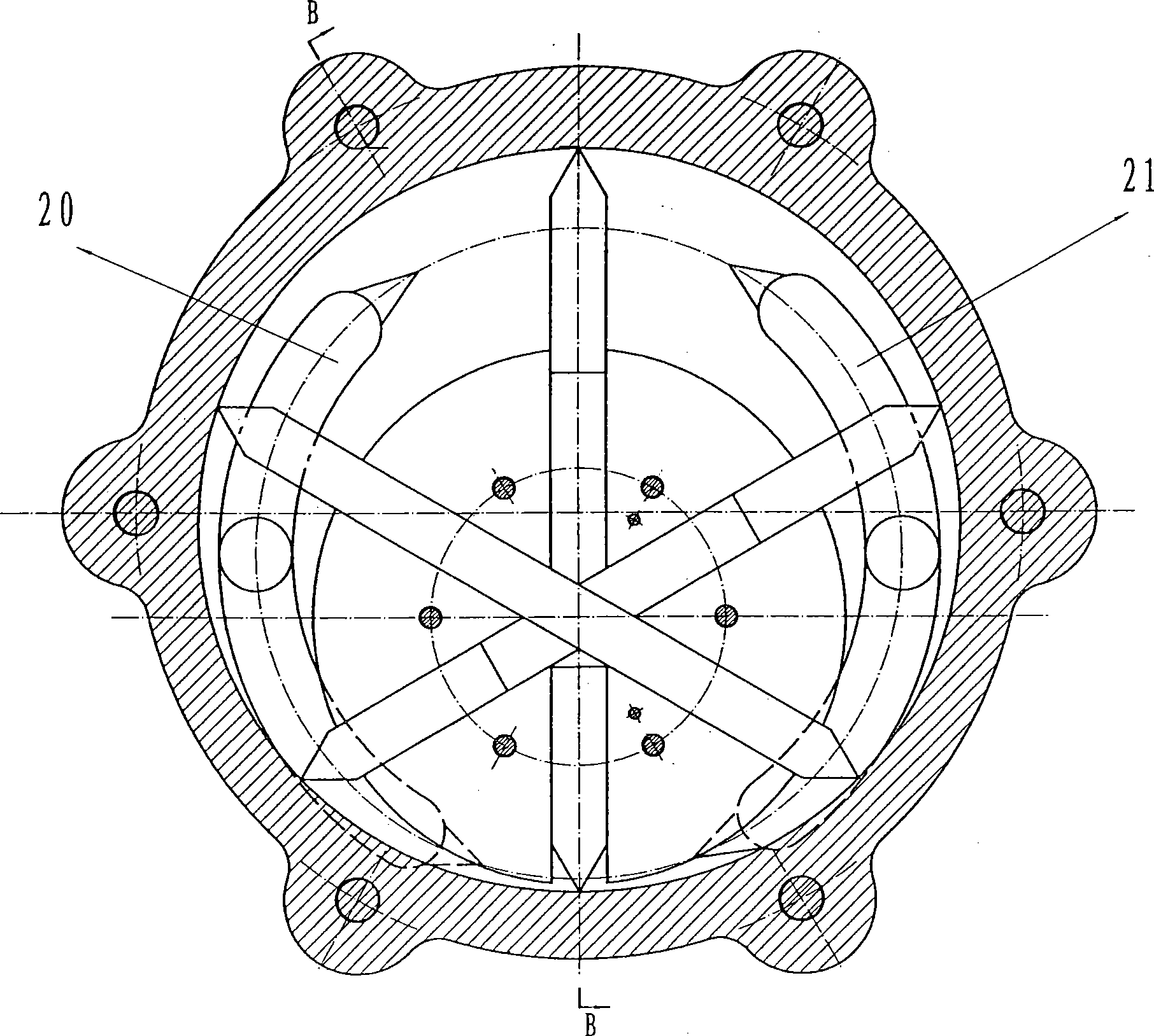
[0020] A non-circular stator inner ring curve single-acting vane pump, mainly composed of a left gland 1, a stator 2, a right gland 3, a gasket 4, a connecting screw 5, a sealing ring 6, a locking screw 7, a right end cover 8, and a screw 9 , positioning pin 10, shaft 11, right vane 12, bearing 13, left end cover 14, dustproof ring 15, rotor shaft 16, retaining ring 17, middle vane 18, left vane 19, the axis of rotor shaft 16 is in the vane pump It is projected into a point in the cross section and coincides with the pole of the non-circular closed curve. The rotor shaft 16 is provided with a radially penetrating blade slot. The length and width of the blade slot are equal to the blade width and thickness. The right blade 12, the middle blade 18, the left blade 19 radially passes through the vane groove of the rotor shaft 16 and can slide freely in the radial direction.

[0021] The polar coordinate equation of the stator inner ring curve is defined as ρ=R+S sinθ, where R=100m...

Embodiment approach 2

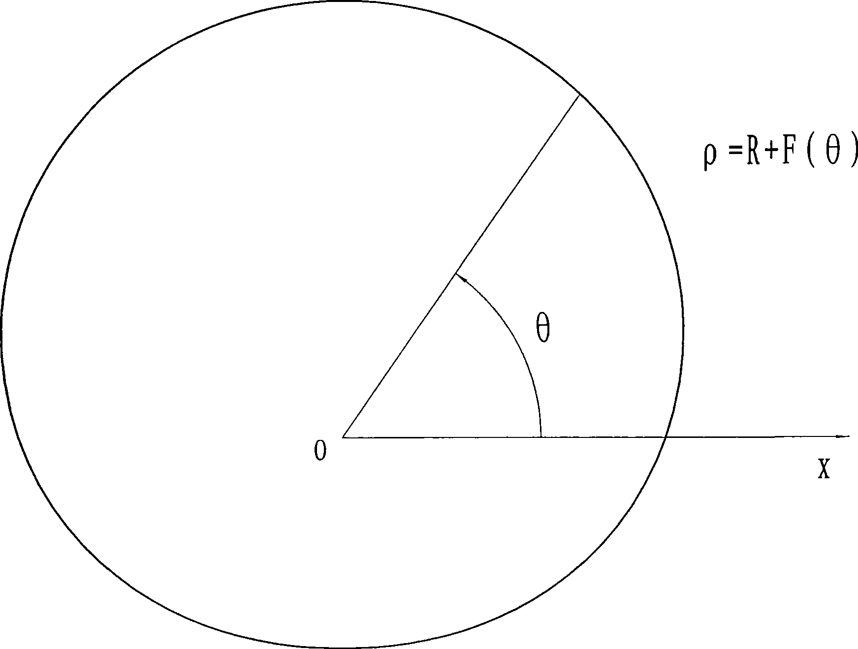
[0024] The polar coordinate equation of the stator inner ring curve is defined as ρ=R+F(θ),

[0025] where R=100mm, F ( θ ) = 16 · θ θ ∈ [ 0 , π 2 ] - 16 · θ + 16 π θ ∈ [ π ...

Embodiment approach 3

[0028] The polar coordinate equation of the stator inner ring curve is defined as ρ=R+F(θ),

[0029] where R=100mm, F ( θ ) = - 10 θ 2 + 10 πθ θ ∈ [ 0 , π ] 10 θ 2 + 20 π 2 - ...


PUM


Abstract

A non-circular stator internal ring curve single-acting vane pump belongs to the field of mechanical design in mechanical engineering, which is a hydraulic pump that the vane is geometrically sealed with the stator and that the vane is tightly jointed with the internal surface of the stator without external force. The stator internal ring curve in the invention is a non-circular closed curve: any straight line is made through the acnode of the non-circular closed curve, the length of the line segment formed by two intersection points of the straight line and the non-circular closed curve is always a definite value, and the polar equation of the non-circular closed curve is as follows: rho equals R plus F (theta); in the formula, rho is polar radius, theta is polar angle, R is constant; and in rectangular coordinate system, F (theta) is continuous periodic function and is symmetrical about the point (phi, 0), the cycle time T is equal to 2 phi, and theta belongs to (0, 2 phi). Compared with the existing vane pump, in the working process of the non-circular stator internal ring curve single-acting vane pump in the invention, the vane radial force is balanced without supplying high pressure oil through the root of the vane groove, that is, oil supply path is not needed; and the pump is simple in structure, and the manufacturing technology is convenient. The non-circular closed curve further can be used for vane hydraulic motors.

Description

technical field [0001] The invention discloses a non-circular stator inner ring curved single-acting vane pump, which belongs to the technical field of mechanical design in mechanical engineering, and is specifically a hydraulic pump with a geometric seal between the vane and the stator. Background technique [0002] At present, in the field of vane pumps, vane pumps balance the radial force of the vane by supplying high-pressure oil to the root of the vane groove. For this reason, an oil supply circuit must be added to the rotor, resulting in increased manufacturing costs and leakage. The close fit between the blade and the inner surface of the stator is guaranteed by the centrifugal force when the blade rotates, which limits the lower limit of the operating speed of the vane pump. Contents of the invention [0003] The purpose of the non-circular stator inner ring curve single-acting vane pump of the present invention is to solve the defect that the vane of the existing ...

Claims


Application Information

Patent Timeline
IPC IPC(8): F04C2/344
Inventor 王志标王燕燕
Owner 王志标
Learn More