Radiator fan

A technology for cooling fans and fan frames, which is applied to electromechanical devices, electrical components, liquid fuel engines, etc., can solve problems such as damage to electronic components, inconvenient use and installation, and difficulty in dissipating heat from the drive device 64.

Inactive Publication Date: 2009-08-19
SUNONWEALTH ELECTRIC MACHINE IND
View PDF1 Cites 6 Cited by
  • Summary
  • Abstract
  • Description
  • Claims
  • Application Information

AI Technical Summary

Problems solved by technology

However, the existing heat dissipation fan with an inner rotor motor must be assembled into the fan frame in actual use, which causes a lot of inconvenience in use and installation.
Moreover, also because the installation position of the driving device 64 (that is, the circuit board) is too close to the stator structure 62, the stator structure 62 is likely to generate high heat when it actually works, causing the driving device 64 to be difficult to dissipate heat, and then it is easy to cause other problems. Associated electronic components are damaged

Method used


Image

  • Radiator fan
  • Radiator fan
  • Radiator fan

Examples


Embodiment Construction

[0039] In order to make the above and other objects, features and advantages of the present invention more clearly understood, preferred embodiments of the present invention will be exemplified below and described in detail in conjunction with the accompanying drawings.

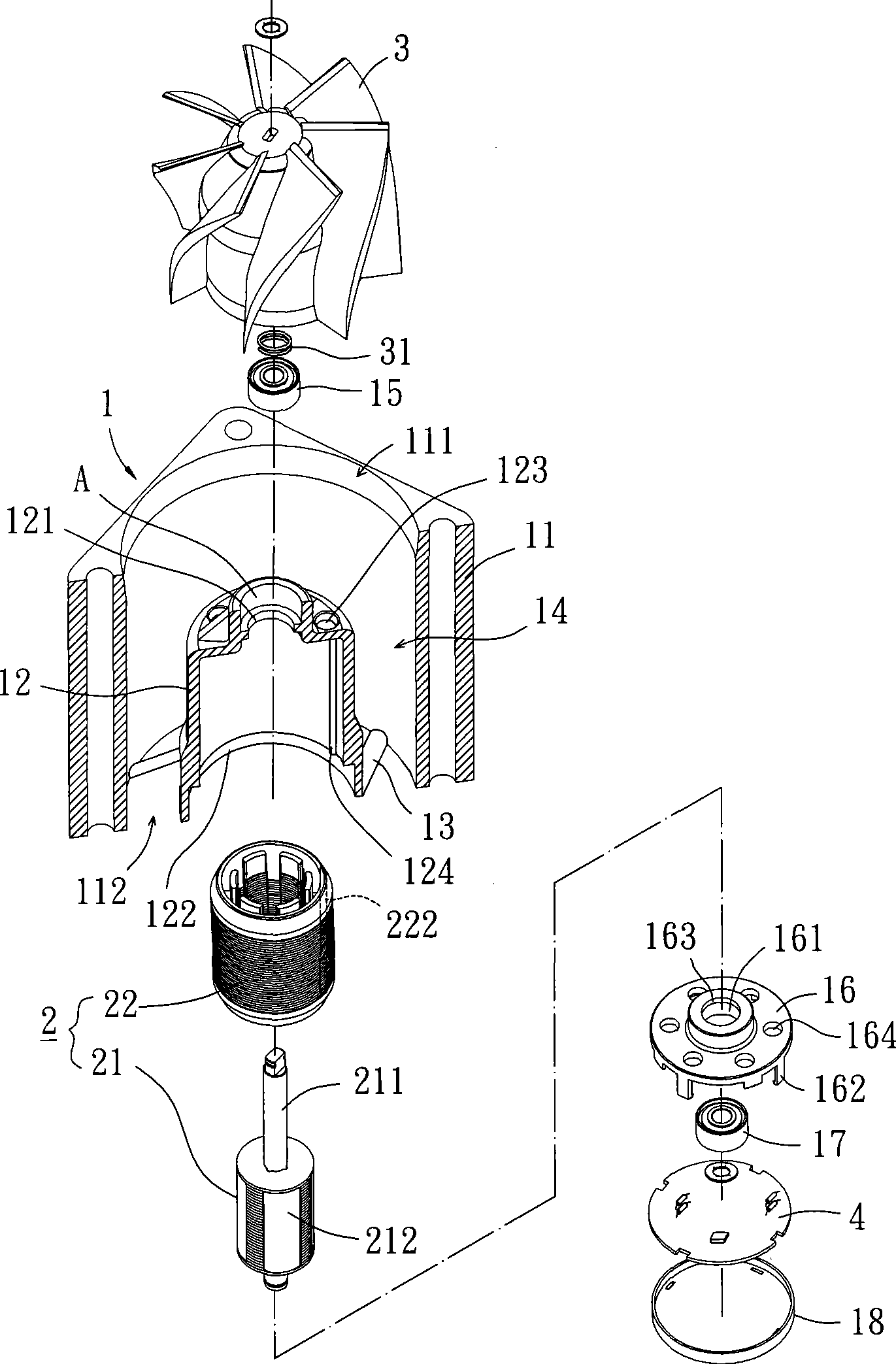
[0040] Such as image 3 As shown, the cooling fan according to the first embodiment of the present invention mainly includes a fan frame 1 , an inner rotor motor 2 , an impeller 3 and a circuit board 4 . The fan frame 1 is an integrally formed frame; the inner rotor motor 2 is arranged inside the fan frame 1; the impeller 3 is combined with the inner rotor motor 2; the circuit board 4 is electrically connected to the inner rotor motor 2 for control The inner rotor motor 2 drives the impeller 3 to rotate.

[0041] The fan frame 1 of the first embodiment of the present invention has an outer frame portion 11, an air inlet 111 and an air outlet 112 are respectively formed at two ends of the outer frame portion ...


PUM


Abstract

The invention relates to a radiator fan, which comprises a fan frame, an inner rotor motor, at least an impeller and a circuit wafer. The fan frame is provided with an outer frame, the inner side of the outer frame forms a hollow motor shell in an integrative molding way. The inner rotor motor is combined with the interior of the motor shell and comprises a rotor and a stator. The rotor is rotatably contained in the stator and is provided with a rotating shaft and a magnetic component. The rotating shaft penetrates out to the outer of the motor shell. The magnetic component is combined with the rotating shaft and is aligned with the stator. The impeller is combined with the rotating shaft and arranged in the external part of the motor shell. The circuit wafer is electrically connected with the stator; thereby, the inner rotor motor can be used for driving the impeller to rotatably move, and then provides better heat dissipation effect.

Description

technical field [0001] The invention relates to a heat dissipation device, in particular to a heat dissipation fan with an inner rotor motor. Background technique [0002] Such as figure 1 Shown is a heat dissipation fan with an external rotor motor in the prior art, and the heat dissipation fan generally includes a fan frame 51 , a stator 52 , a circuit board 53 and a rotor 54 . The inner side of the fan frame 51 is provided with a shaft tube 511, and at least one bearing 512 is arranged in the shaft tube 511; the stator 52 and the circuit board 53 are sleeved on the outer peripheral surface of the shaft tube 512, and the circuit board 53 is electrically Connect the stator 52; the rotor 54 has a rotating shaft 541 and an impeller 542, the rotating shaft 541 extends to the shaft tube 511 to pivotally connect the bearing 512, the impeller 542 is combined with one end of the rotating shaft 541, and the impeller 542 One permanent magnet 543 corresponding to the stator 52 is p...

Claims


Application Information

Patent Timeline
Patent Type & Authority Applications(China)
IPC IPC(8): F04D25/08F04D29/00H02K1/12H02K1/27H02K5/04
Inventor 洪银树尹佐国
Owner SUNONWEALTH ELECTRIC MACHINE IND
Why Eureka
Try Eureka