Flow control valve of large-sized low temperature device

A low-temperature device and flow control technology, applied in valve devices, lift valves, valve details, etc., can solve the problems of lack of liquid helium in low-temperature devices, large valve heat leakage, waste of helium, etc., and reduce radiation heat transfer. and radial heat conduction, solve heat leakage and leakage, reduce the effect of heat conduction

Inactive Publication Date: 2009-08-19
INST OF PLASMA PHYSICS CHINESE ACAD OF SCI
View PDF0 Cites 15 Cited by
  • Summary
  • Abstract
  • Description
  • Claims
  • Application Information

AI Technical Summary

Problems solved by technology

The traditional flow control valves for cryogenic devices mainly have the following defects: 1. There are two shortcomings in heat leakage and leakage. Large heat leakage often leads to large heat load on the valve and severe frosting; high leakage rate will cause economic losses to the enterprise
2. The heat insulation measures are not in place, such as not vacuuming, not adding heat insulating materials, etc. These defects have caused the heat leakage of the valve to be too large, and sometimes even the complete evaporation of liquid helium due to the excessive heat load of the valve itself makes the cryogenic device no liquid helium
3. There may be no leakage problem when adjusting the flow rate of liquid nitrogen or other liquids with a higher boiling point temperature, but when controlling the flow rate of low-temperature helium, especially high-pressure supercritical helium, the leakage rate is often relatively large, resulting in waste of helium

Method used


Image

  • Flow control valve of large-sized low temperature device

Examples


Embodiment Construction

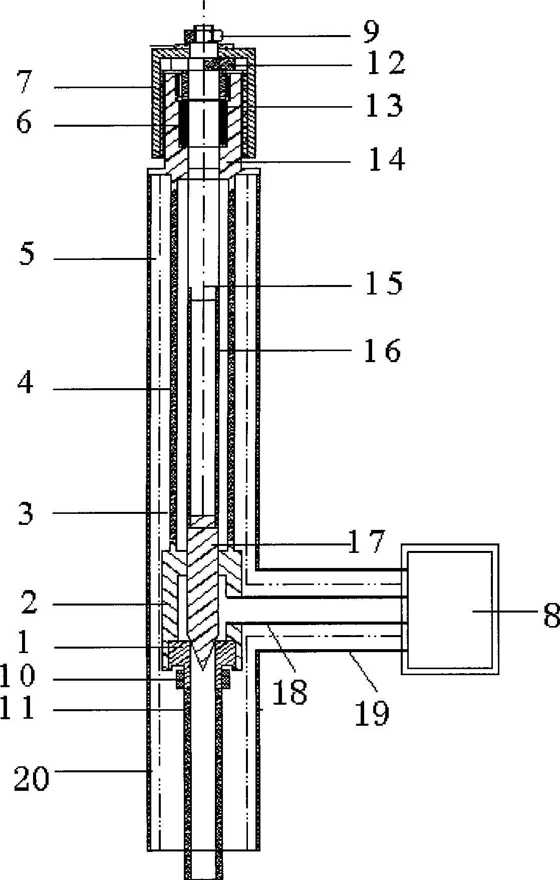
[0015] A flow control valve for a large cryogenic device, including a valve seat 1, a valve core 17 and a valve body 2, and a vacuum valve sleeve outer tube 5, the upper ends of the vacuum valve sleeve outer tube 5 and the vacuum valve sleeve inner tube 4 are connected with a valve cover 14. There is a stepped hole in the middle of the bonnet 14, and a valve stem 15 is slidingly fitted in the stepped hole, and there is a Teflon material between the outer wall of the valve stem 15 and the wall of the stepped hole of the bonnet 14. The sealing ring 6, the sealing ring 6 is located in the sealing groove 13 on the step hole, the upper end of the step hole has an internal thread, the sealing ring pre-tightening bolt 12 with a middle opening is set outside the valve stem 15, the sealing ring pre-tightening bolt 12 Screwed with the internal thread on the stepped hole, the sealing ring pre-tightening bolt 12 is pressed on the sealing ring 6; the upper end of the valve stem 15 is fixed ...


PUM


Abstract

The invention discloses a flow control valve of a large low-temperature device, comprising a vacuum valve sleeve; the upper end of an outer tube of the vacuum valve sleeve is connected with a valve cover; a step hole is opened in the center of the valve cover; the step hole is internally provided with a slide-fit valve rod; a bonnet is fixed at the upper end of the valve rod; the bonnet and the valve cover are connected by a thread; an inner tube of the vacuum valve sleeve is sheathed outside the valve rod without contact; the upper end of the vacuum valve sleeve inner tube is connected with the lower end of the valve cover; the lower end of the vacuum valve sleeve inner tube is connected with a valve body; the lower end of the valve body is fixedly connected with a valve seat; a liquid outlet is opened at the lateral wall of the cylinder-shaped valve body; the liquid outlet is connected with an inner tube of a low-temperature device connecting tube; a vacuum valve sleeve outer tube, a vacuum perfusion tube outer tube and a low-temperature device connecting tube outer tube are welded together and processed by vacuumization together; a valve core penetrates the valve body from top to bottom, the cone-shaped lower end of the valve core is pressed against the valve mouth of the valve seat, and the lower end of the valve mouth is connected with a vacuum perfusion tube inner tube. The invention excellently resolves the problems of heat leakage and leakage, namely, the valve can not be frosted when regulating liquid helium flow, and the valve does not leak when regulating cold helium and high-pressure supercritical helium flow.

Description

Technical field: [0001] The invention mainly relates to a valve, in particular to a flow control valve for a large cryogenic device. Background technique: [0002] The flow control valves for cryogenic devices currently on the market are all designed for the temperature range of liquid nitrogen (77K), and there are few valves that are actually used for flow control of liquid helium (4.2K) in large cryogenic devices. Traditional cryogenic device flow control valves mainly have the following defects: 1. There are two shortcomings in heat leakage and leakage. Large heat leakage often leads to large heat load on the valve and serious frosting; high leakage rate will cause economic losses to the enterprise. 2. The heat insulation measures are not in place, such as not vacuuming, not adding heat insulating materials, etc. These defects have caused the heat leakage of the valve to be too large, and sometimes even the complete evaporation of liquid helium due to the excessive heat l...

Claims


Application Information

Patent Timeline
Patent Type & Authority Applications(China)
IPC IPC(8): F16K27/02F16K1/38F16K25/00F16K41/02
Inventor 任志斌武玉彭晋卿
Owner INST OF PLASMA PHYSICS CHINESE ACAD OF SCI
Why Eureka
Try Eureka