Passive clamping voltage boosting type interleave parallel connection converter implemented by coupling inductance and switch capacitance

A technology of coupled inductors and switched capacitors, which is applied in the field of DC-DC converters, can solve the problems of high output diode voltage stress, failure to realize the high gain function of the converter, and failure to reduce the voltage stress of the power switch tube, so as to achieve the goal of increasing the voltage gain Effect

Active Publication Date: 2009-08-19
ZHEJIANG UNIV
View PDF0 Cites 24 Cited by
  • Summary
  • Abstract
  • Description
  • Claims
  • Application Information

AI Technical Summary

Problems solved by technology

Although these two methods can realize the soft switching of the power switch tube, the external circuit is complicated, and the voltage stress of the power switch tube cannot be reduced, and the high gain function of the converter cannot be realized.
In order to improve the voltage gain of the converter, one way is to use series switched capacitor units. This method needs to connect multiple switched capacitor units in series to achieve high-gain conversion, and the circuit is more complicated; the other way is to use three-winding coupled inductors. In this mode, the output diode voltage stress is high, which affects the efficiency of the converter

Method used


Image

  • Passive clamping voltage boosting type interleave parallel connection converter implemented by coupling inductance and switch capacitance
  • Passive clamping voltage boosting type interleave parallel connection converter implemented by coupling inductance and switch capacitance
  • Passive clamping voltage boosting type interleave parallel connection converter implemented by coupling inductance and switch capacitance

Examples


Embodiment Construction

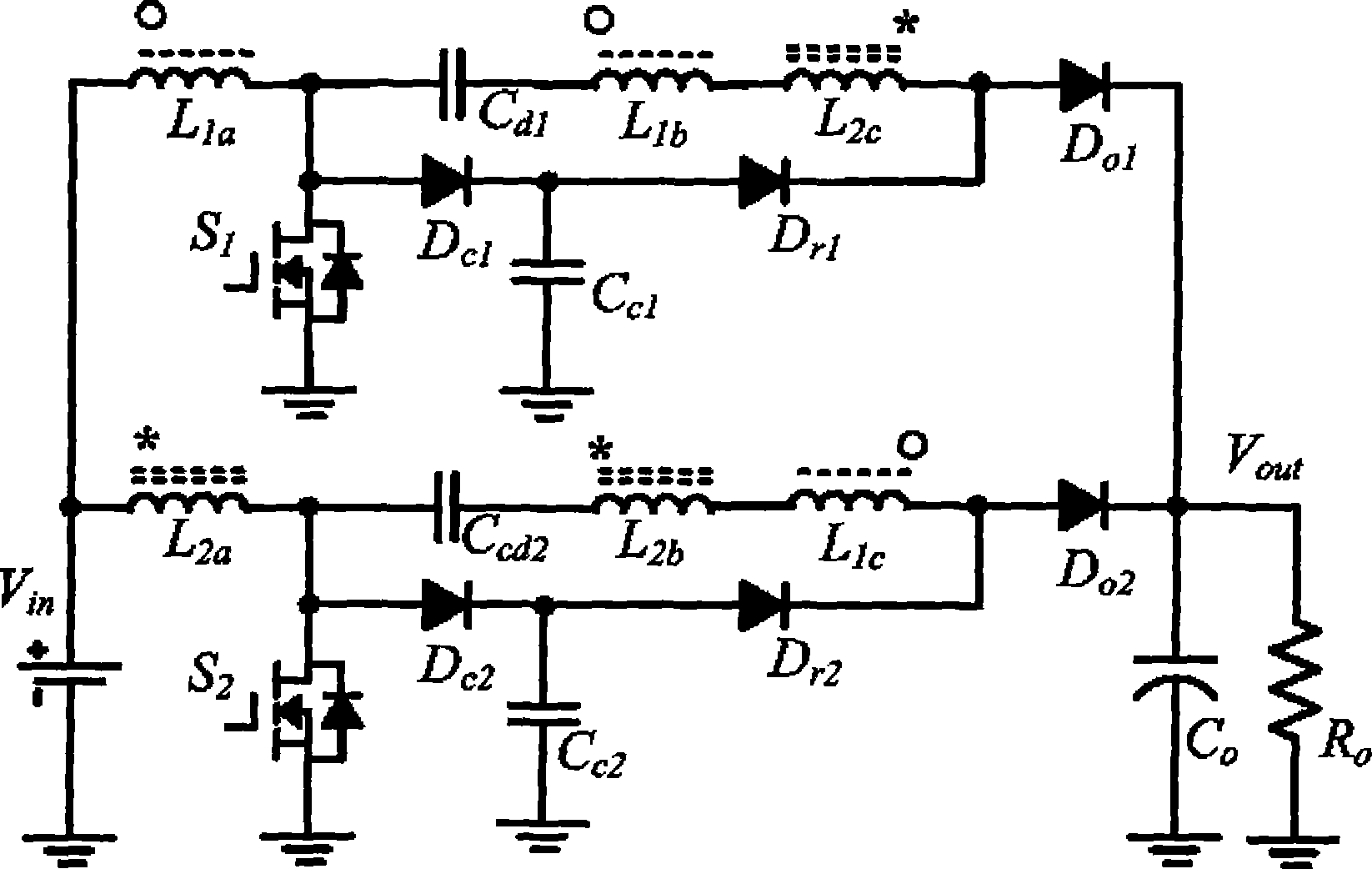
[0010] see figure 1 , the coupled inductor and switched capacitor of the present invention realize the passive clamp boost type interleaved parallel converter, including two power switch tubes S1, S2, two clamp diodes Dc1, Dc2, two clamp capacitors Cc1, Cc2, Two freewheeling diodes Dr1, Dr2, two switching capacitors Cd1, Cd2, two output diodes Do1, Do2, one output capacitor Co and two coupling inductors, the first coupling inductor has three windings L1a, L1b, L1c, the second The coupled inductor has three windings L2a, L2b, and L2c. One end of the first winding L1a of the first coupled inductor is connected to one end of the first winding L2a of the second coupled inductor and the positive end of the power supply Vin. The first winding of the first coupled inductor The other end of L1a is connected to the source of the first power switch tube S1, the anode of the first clamping diode Dc1 and one end of the first switching capacitor Cd1, and the cathode of the first clamping d...


PUM


Abstract

The invention discloses a boost type staggered parallel converter for realizing passive clamping by combining a coupled inductor and a switch capacitance. The boost type staggered parallel converter comprises two power switch pipes, two clamping diodes, two clamping capacitors, two free wheeling diodes, two switched capacitors, two output diodes, an output capacitor and two coupled inductors, wherein the two coupled inductors have three windings respectively. The leakage inductance of the two coupled inductors is used for realizing the zero-current turning-on of the power switch pipes, the passive clamping circuit consisting of the clamping diodes and the clamping capacitor is used for realizing the soft turning-off of the power switch pipes and the lossless transfer of the leakage inductance power, the clamping diodes have no series connection with a power loop, thus reducing the conductive loss, the second winding and the third winding of the two coupled inductors are used for realizing high gain output of the convertor, the two switch capacitors are used for further raising the voltage gain of the convertor and reducing the voltage stress of the power devices, and no extra power switches and conductive components are needed. The circuit has no energy consumption components but simple structure.

Description

technical field [0001] The invention relates to a DC-DC converter. Specifically, coupled inductors and switched capacitors are used to realize passive clamping step-up interleaved parallel converters. Background technique [0002] A conventional step-up (Boost) interleaved parallel DC-DC converter includes two inductors, two freewheeling diodes, two power switch tubes, the drain of the first power switch tube and the anode of the first diode and One end of the first inductance is connected, the drain of the second power switch tube is connected with the anode of the second diode and one end of the second inductance, and the other end of the first inductance is connected with the other end of the second inductance. The output voltage gain of this step-up interleaved parallel DC-DC converter is small, the voltage stress of the power switch tube is large, the power switch tube works as a hard switch, the switching loss is large, and the reverse recovery current of the freewhee...

Claims


Application Information

Patent Timeline
Patent Type & Authority Applications(China)
IPC IPC(8): H02M3/04H02M3/06H02M3/10
Inventor 何湘宁李武华
Owner ZHEJIANG UNIV
Why Eureka
Try Eureka