Blood sensor and blood examining instrument including same

A blood test, sensor technology

Inactive Publication Date: 2009-08-19
PANASONIC HEALTHCARE HLDG CO LTD
View PDF2 Cites 4 Cited by
  • Summary
  • Abstract
  • Description
  • Claims
  • Application Information

AI Technical Summary

Problems solved by technology

At this time, the blood 15 is not supplied to the supp

Method used


Image

  • Blood sensor and blood examining instrument including same
  • Blood sensor and blood examining instrument including same
  • Blood sensor and blood examining instrument including same

Examples


Embodiment approach 1

[0083] Figure 4 An example of the blood sensor of the present invention (Embodiment 1) is shown through FIG. 8 .

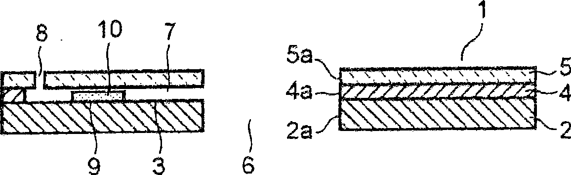
[0084] Figure 4 It is a sectional view of blood sensor 20a of Embodiment 1. Blood sensor 20 a has a plate shape and is composed of substrate 21 , spacer 22 attached to the upper surface of substrate 21 , and cover 23 attached to the upper surface of spacer 22 .

[0085] The blood storage part 24 is formed by communicating a substrate hole 21 a formed approximately in the center of the substrate 21 , a spacer hole 22 a formed approximately in the center of the spacer 22 , and a cover hole 23 a formed approximately in the center of the cover 23 . formed space. The blood storage part 24 is perforated downward or upward.

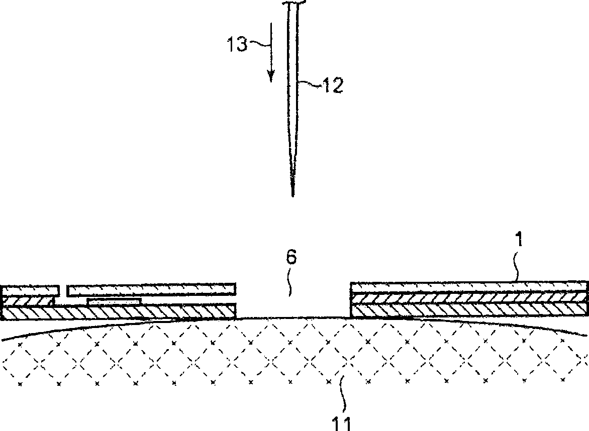
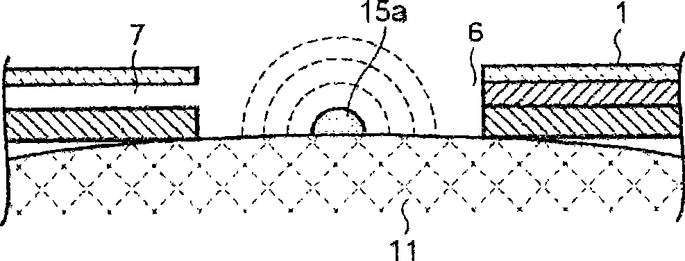
[0086] The lower surface of the substrate 21 of the blood sensor 20 a is brought into contact with the skin, and the skin in the blood storage part is punctured, whereby blood from the skin accumulates in the blood storage part 24 . One end o...

Embodiment approach 2

[0111] 9 and 10 show blood sensor 20b according to the second embodiment.

[0112] Blood sensor 20 b is different from blood sensor 20 a of Embodiment 1 in that groove 26 a is formed between substrate 21 and cover 23 . Hereinafter, this difference will be mainly described, and the same components as in Embodiment 1 will be given the same reference numerals and briefly described.

[0113] Figure 9A is a sectional view of the blood storage part 24 of the blood sensor 20b and its vicinity, Figure 9B is its perspective plan view. The diameter 21e of the substrate hole 21a formed in the substrate 21 is 1.6 mm. The diameter 22e of the spacer hole 22a formed in the spacer 22 is 2.0mm. Furthermore, the diameter 23e of the cover hole 23a formed in the cover 23 is 1.0 mm. The respective centers of the substrate hole 21a, the spacer hole 22a, and the cover hole 23a are on the same axis.

[0114] The blood storage part 24 of the blood sensor 20b is the same as the first embodiment...

Embodiment approach 3

[0120] 11 and 12 show blood sensor 20c according to the third embodiment.

[0121] Groove 26b similar to groove 26a of blood sensor 20b in Embodiment 2 is formed between substrate 21 and cover 23 of blood sensor 20c. However, unlike the groove 26a, the groove 26b is formed on the side of the supply path 25, and no groove is formed on the opposite side 24e of the supply path 25. Hereinafter, this difference will be mainly described, and the same components as those in the blood sensor 20b of Embodiment 2 will be given the same reference numerals and briefly described.

[0122] Figure 11A is a sectional view of the blood storage part 24 of the blood sensor 20c and its vicinity, Figure 11B is its perspective plan view. The diameter 21f of the substrate hole 21a formed in the substrate 21 is 1.8 mm. The diameter 22f of the spacer hole 22a formed in the spacer 22 is 2.0 mm. Furthermore, the diameter 23f of the cover hole 23a formed in the cover 23 is 1.0 mm.

[0123] The ce...


PUM

PropertyMeasurementUnit
Thicknessaaaaaaaaaa
Thicknessaaaaaaaaaa
Thicknessaaaaaaaaaa

Abstract

A blood sensor (20a) comprises a substrate (21); a spacer (22) attached to the top of the substrate (21); a cover (23) attached to the top of the spacer (22); a blood reservoir portion (24) defined by a substrate hole (21a) formed in the substrate (21), a part of a spacer hole (22a) formed in the spacer (22) and connected to the substrate hole (21a), and a cover hole (23a) formed in the cover (23) and connected to the spacer hole (22a); a supply passage (25) defined by another part of the spacer hole (22a) and communicating with the blood reservoir portion (24); and detection electrodes formed in the supply passage (25). The cover (23) projects from the supply passage (25) toward the inside of the blood reservoir portion (24) farther than the substrate (21) and the spacer (22).

Description

technical field [0001] The present invention relates to a blood sensor and a blood test device for performing blood tests using the blood sensor. Background technique [0002] Diabetics need to regularly measure blood sugar levels and inject insulin based on the measured blood sugar levels to maintain normal blood sugar levels. In order to maintain this normal blood sugar level, it is necessary to measure the blood sugar level frequently, for which a small amount of blood is collected from a patient's fingertip or the like using a blood test device. A blood sensor is used to detect a blood sugar level from collected blood. [0003] use Figure 1 to Figure 3 A conventional blood sensor will be described (see Patent Document 1). figure 1 The shown blood sensor 1 includes: a plate-shaped substrate 2; a substrate hole 2a formed on the substrate 2; a plurality of detection electrodes 3 formed on the substrate 2; a spacer 4 mounted on the upper surface of the substrate 2 Gaske...

Claims


Application Information

Patent Timeline
IPC IPC(8): A61B5/151A61B5/1473G01N27/416A61B5/15G01N33/66A61B5/157G01N27/28
CPCG01N27/3272A61B5/1486A61B5/1411A61B5/14535G01N33/66A61B5/14532A61B5/150022A61B5/150099A61B5/150213A61B5/150358A61B5/150412A61B5/150503A61B5/150954A61B5/15109A61B5/15113A61B5/15117A61B5/15136A61B5/1519A61B5/157A61B5/1405G01N27/416
Inventor 藤原雅树秋山敏博滨中健一
Owner PANASONIC HEALTHCARE HLDG CO LTD
Why Eureka
Try Eureka