Switch apparatus especially compact starter

A technology of switchgear and switch position, which is applied in protection switches, parts of protection switches, emergency protection devices, etc., and can solve problems such as device damage

Inactive Publication Date: 2009-08-19
SIEMENS AG
View PDF0 Cites 1 Cited by
  • Summary
  • Abstract
  • Description
  • Claims
  • Application Information

AI Technical Summary

Problems solved by technology

The downside is that the contactor must be replaced after a short circuit condition
The result may be severe damage to the unit

Method used


Image

  • Switch apparatus especially compact starter
  • Switch apparatus especially compact starter
  • Switch apparatus especially compact starter

Examples


Embodiment Construction

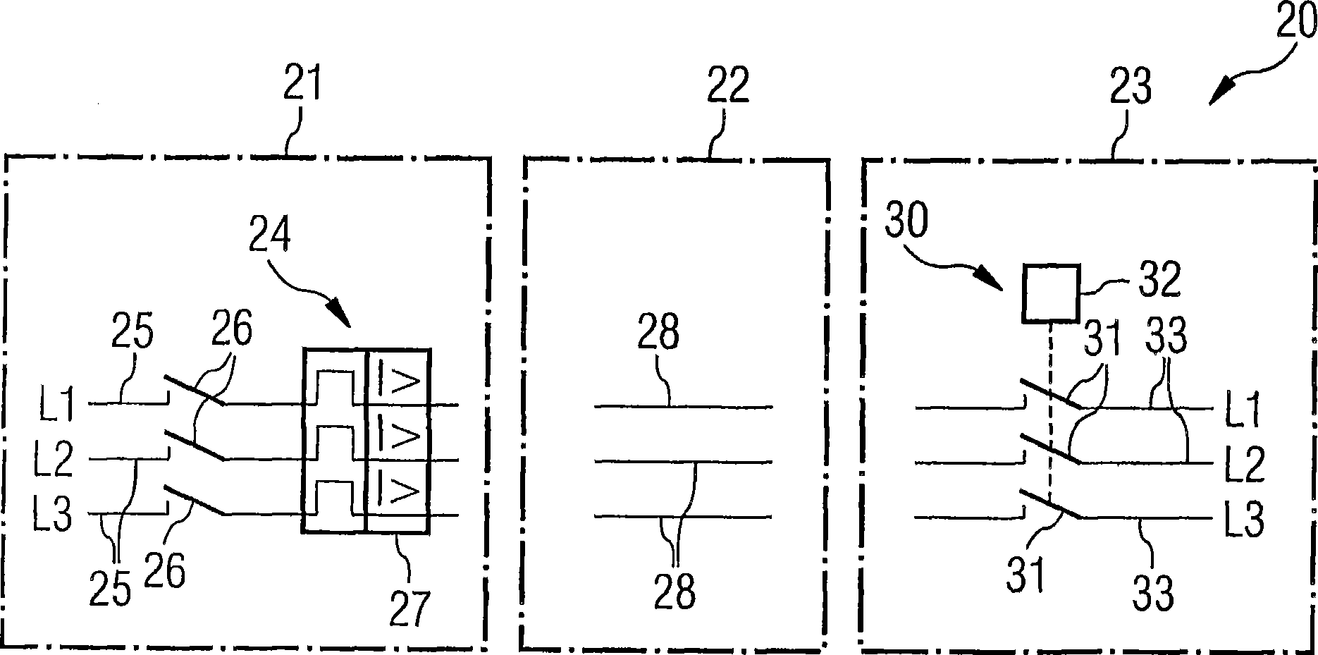
[0062] figure 1 It is a circuit diagram of a series connection 20 formed by two independent series switching devices 21 , 23 in the prior art. figure 1 The first switching device 23 on the right has a first switching position 30 . The first switching point 30 is, for example, a contactor and has a switching drive (more precisely, a control magnet 32 ​​) for actuating the main contact 31 . figure 1 The two switching devices 21 , 23 shown are designed as three-pole switching devices. Reference symbols L1 - L3 designate current paths or power lines which can be switched off or connected by means of the first switch position 30 . Reference numeral 33 denotes the electrical equipment side leads of the current paths L1-L3. Reference numeral 25 designates grid-side leads of the current paths L1-L3.

[0063] figure 1 The left side of is the second switching device 21 with the second switching position 24 . The second switch position 24 is, for example, a short-circuit switch or ...


PUM


Abstract

The switching device (1) has a first switching point (2) for normal switching of at least one current path (L1-L3), and has a second switching path (3) for disconnection of a short-circuit current. The first and second switching points (2, 3) are connected in series, and are accommodated in a common enclosure (G). Electrical connections (IN, OUT) and, if required, a control connection (CON) for inputting a switching command, are provided in or on the enclosure (G), for connection of the current paths (L1-L3). The first switching point (2) is designed for a maximum continuous current. The second switching point (3) is designed to disconnect a short-circuit current which is a multiple of the maximum continuous current. The first switching point (2) has at least one main contact (9) which can withstand a short-circuit at least for the time (Delta T) by means of a contact holding system (A) or a contact locking system (Z).

Description

technical field [0001] The invention relates to a switching device having a first switching position and a second switching position. The first switch position is used for on-off operation of at least one current path in a normal working state, and the second switch position is used for cutting off the short-circuit current. The first and second switch positions are connected in series. Background technique [0002] With the help of switchgear (especially low-voltage switchgear), the current path between the power supply equipment and the electrical equipment can be switched on and off, and then its working current can be switched on and off. That is to say, by using the switching device to disconnect and connect the current path, the electrical equipment connected to the current path can be safely and reliably switched on and off. [0003] The low-voltage switching electrical equipment has more than one main contact for switching the current path, and the main contact can...

Claims


Application Information

Patent Timeline
Patent Type & Authority Applications(China)
IPC IPC(8): H01H89/06H02H7/22
CPCH01H2089/065H01H89/06H01H71/504
Inventor 诺贝特·米特勒梅尔诺贝特·齐默尔曼
Owner SIEMENS AG
Why Eureka
Try Eureka