
An external flag staff lifter

A lifter, flagpole technology, applied in the direction of lifting device, building type, building, etc., can solve the problems of high production cost, complex structure, inconvenient maintenance, etc., and achieve the effect of simple structure

Inactive Publication Date: 2009-08-26
尹永志
View PDF0 Cites 5 Cited by
  • Summary
  • Abstract
  • Description
  • Claims
  • Application Information

AI Technical Summary

Problems solved by technology

[0002] There are few types of existing electric external flagpole lifters, some of which cannot control the lifting time, and cannot be synchronized with the length of the music. Even if the purpose of synchronous lifting is achieved, its structure is relatively complicated, and the failure rate is high. Inconvenient, and the production cost is high, it is not suitable for the needs of the modern market. It needs further improvement in the field of automatic control of the lifting flag. It is urgent to introduce a 220-volt voltage control, which can also be controlled by batteries. In the case of power failure, without affecting the lifting speed, it can be converted into battery-driven lifting immediately, so as to meet the needs of the modern market

Method used


Image

  • An external flag staff lifter
  • An external flag staff lifter
  • An external flag staff lifter

Examples


Embodiment Construction

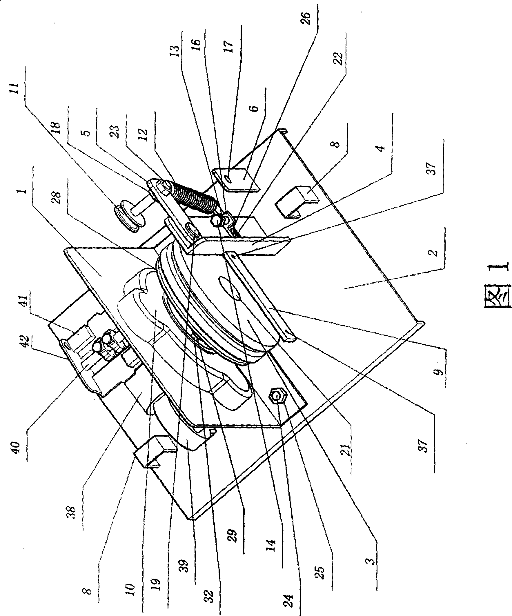
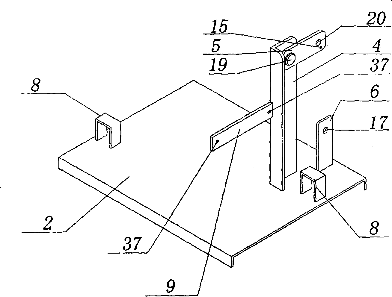
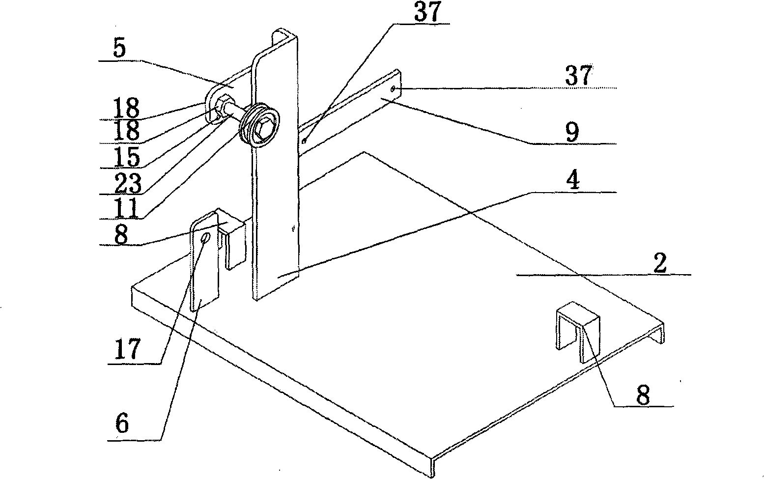
[0024] Such as figure 1 As shown, the bracket plate 1 is fixed to the middle of the base 2 with a fixing screw B24 and a fixing nut C25. Such as figure 2 , image 3 As shown, a fixing frame 4, a clutch frame 6 and two outer cover lock grooves 8 are also welded on the upper part of the base 2. Combine figure 1 , figure 2 , image 3 , Picture 11 As shown, a gear transmission structure is arranged inside the gear cover 10. The gear transmission structure consists of a central shaft gear 51 in the middle of the support plate 1 and a limit gear 50 fixedly meshing with the motor gear 53 in a clutch manner. The central shaft gear 51 is installed on the central shaft, and the central shaft is welded to the bracket plate 1. Such as Figure 4 , Figure 5 As shown, a fixed screw C30 is provided on the central shaft gear 51, a hole for passing through the fixed screw C30 is provided in the middle of the disc 28, and the disc 28 is locked with a fixed nut D29. The fixed screw D32 on the ma...


PUM


Abstract

An external flag staff lifter includes a fixed support disposed on the upper part of a base, a clutch bracket, a housing lock groove and a support plate at the middle of the base, wherein, a lifting line wound onto a main wheel is connected with the upper end and the lower end of the flag staff after passing through a line pressing wheel A, the groove of a line pressing wheel and the line pressing wheel groove at the upper part of the flag staff. A gear drive mechanism is arranged in a gear cover on one side of the support plate and is fixedly engaged with a limit gear and is clutch engaged with a motor gear via a central shaft gear mounted onto a central shaft. The central shaft is welded or fixed with the support plate in the other manners; limiter, a main motor, a speed reducer and a clutch of the speed reducer are arranged on the other side of the support plate. The lifter of the invention is installed outside the flag staff, the lifting time is synchronous with the length of music, the lifting process can be controlled by 220V voltage or by battery, thereby, during in the lifting process, when the power is cut off, the lifting can be driven by battery without influencing the lifting speed.

Description

Technical field [0001] The invention relates to a lifting controller for raising and lowering flags, in particular to an external flagpole lifter which is arranged on the outside of the flagpole and can raise and lower the flag synchronously with music. Background technique [0002] The existing electric external flagpole lifters have fewer types, and some cannot control the lifting time, so they cannot be lifted synchronously with the length of the music. Even if the purpose of synchronous lifting is achieved, the structure is relatively complicated, the failure rate is high, and maintenance is high. Inconvenient and high production cost, it is no longer suitable for the needs of the modern market. In the field of automatic control of lifting flags, further improvement is needed. It is urgent to introduce a 220V voltage control that can also be controlled by batteries. During the lifting process, if you encounter The power outage can be converted into battery-driven lifting with...

Claims


Application Information

Patent Timeline
IPC IPC(8): B66F11/00E04H12/32
Inventor 尹永志
Owner 尹永志
Learn More