Current sampling circuit used for frequency converter and sampling method thereof

A technology of current sampling and frequency converter, applied in the field of frequency conversion control, can solve the problems of expensive, bulky and difficult to integrate

Inactive Publication Date: 2009-08-26
宁波德业变频技术有限公司
View PDF0 Cites 31 Cited by
  • Summary
  • Abstract
  • Description
  • Claims
  • Application Information

AI Technical Summary

Problems solved by technology

Commonly used current sensors are Hall effect detectors, which are not ...

Method used


Image

  • Current sampling circuit used for frequency converter and sampling method thereof
  • Current sampling circuit used for frequency converter and sampling method thereof
  • Current sampling circuit used for frequency converter and sampling method thereof

Examples


Embodiment 1

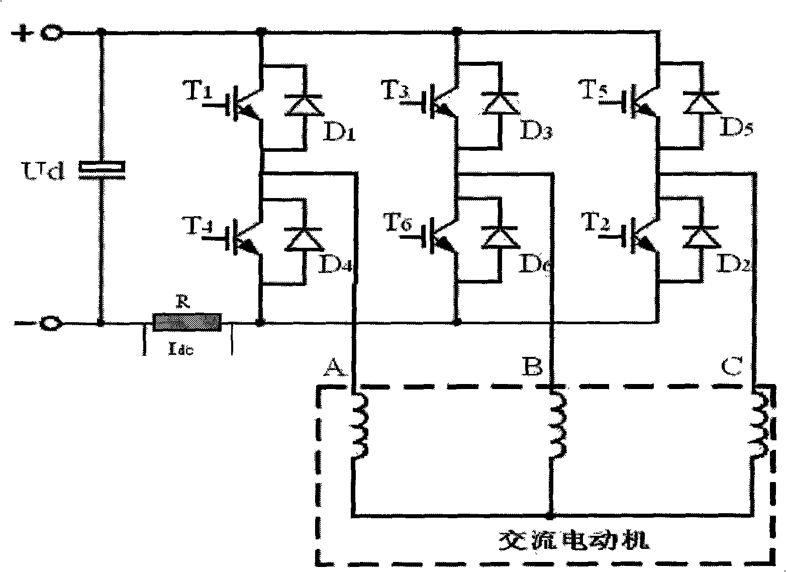
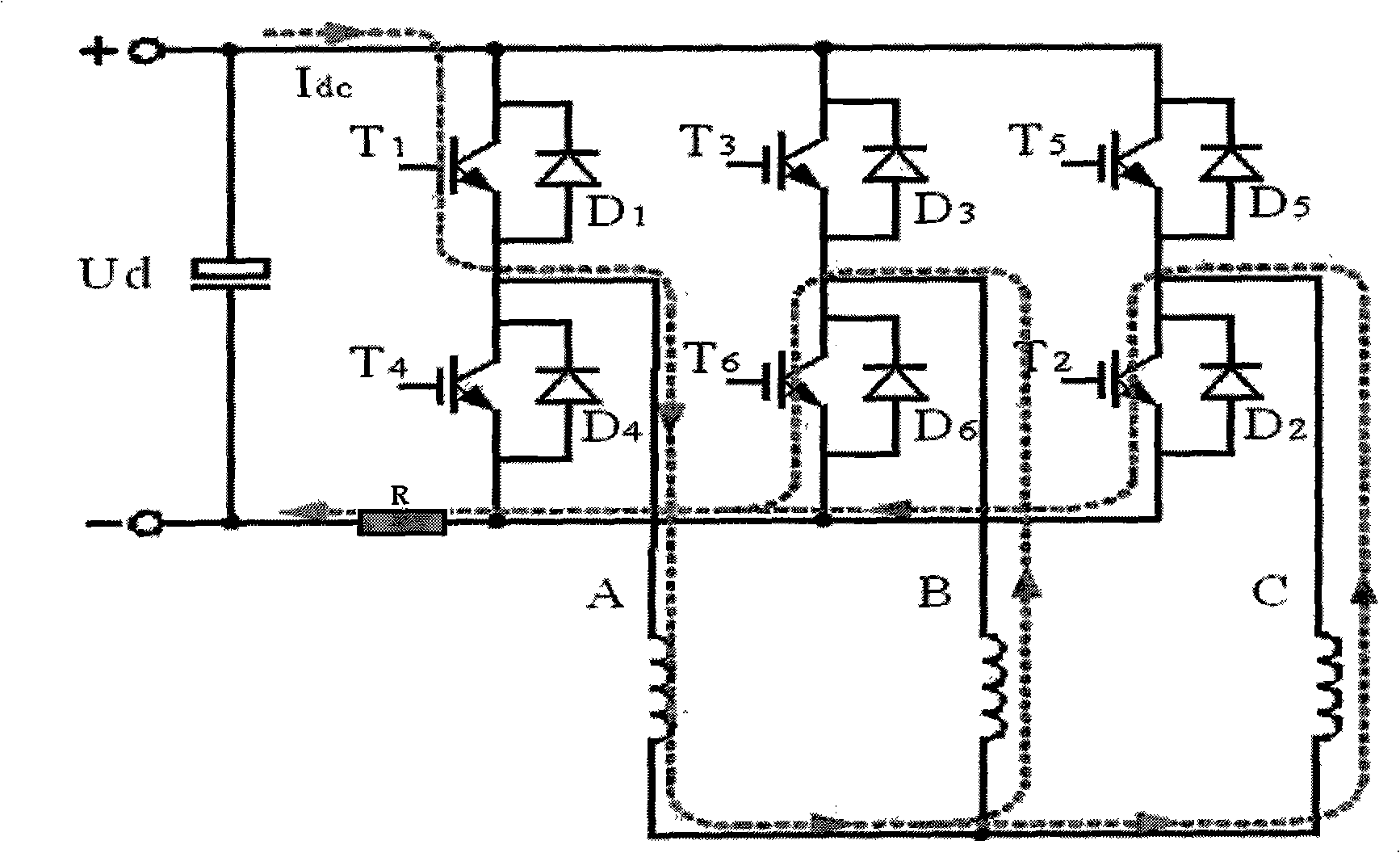
[0024] Embodiment 1: DC bus single resistance sampling

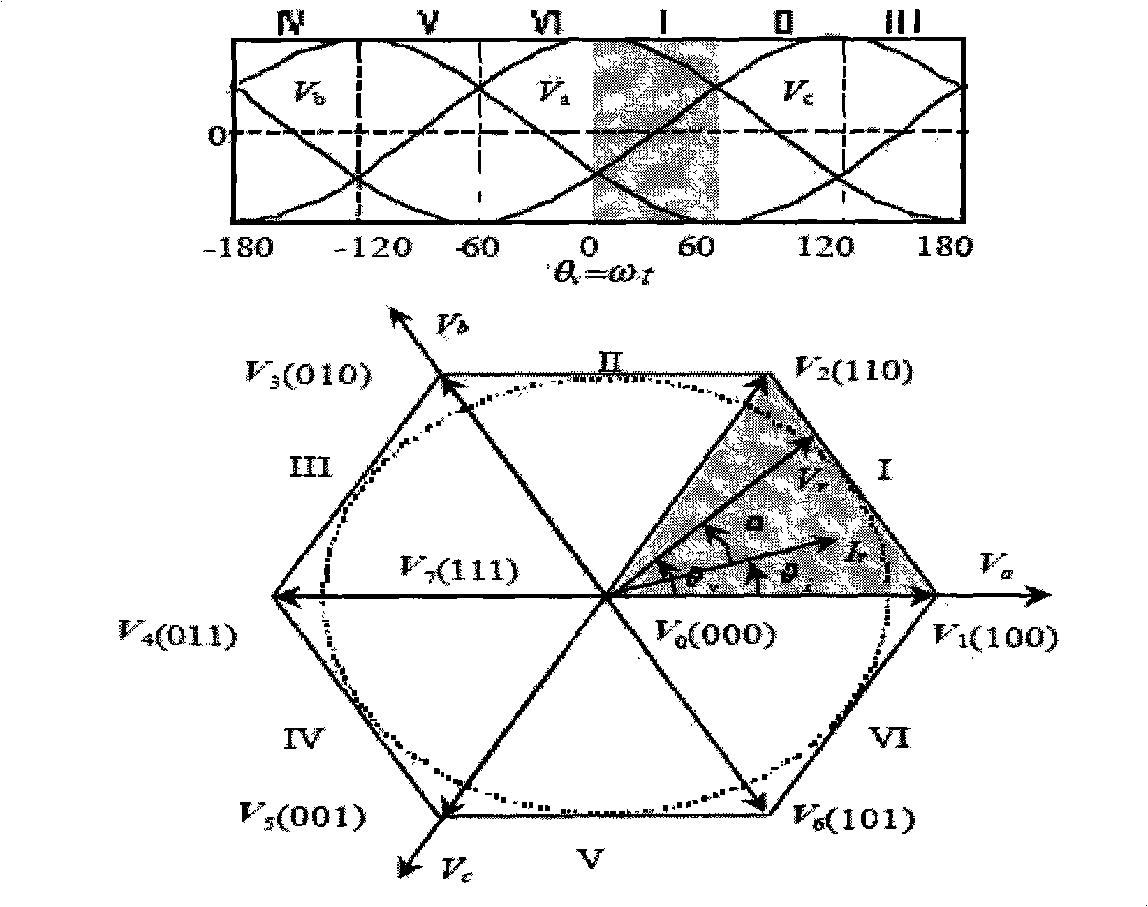
[0025] The structural block diagram of the DC bus single resistance sampling circuit is as follows: figure 1 As shown, through the sampling resistor R connected in series with the negative terminal of the DC bus, the electrical information of the DC bus current Idc is collected, and then according to the switching states of the six switching tubes T1-T6, and combined with the space vector PWM modulation algorithm, the three-dimensional structure of the motor is reconstructed. Phase current A, B, C. The sampling resistor just utilizes the overcurrent protection resistor of the IPM power module, so it will not increase any hardware cost. The traditional current detection method is to use a current sensor to detect the current, but the more expensive sensor increases the system cost. Another method is to use multiple cheap linear resistors to obtain current information, but it is sometimes difficult to realize under the c...

Embodiment 2

[0053] Embodiment 2: Three-resistance phase current sampling of the lower bridge arm of the inverter

[0054] Such as Figure 7 As shown, in this embodiment, a sampling resistor R1, R2, and R3 are respectively connected in series at the output end of the lower bridge arm of each phase of the inverter. When the load current of the motor flows through the lower bridge arm, the three-phase motor can be directly sampled. load current information. These three sampling resistors also take into account the overcurrent protection function of the IPM power module. Compared with Embodiment 1, Embodiment 2 is relatively easy to implement in software, has a simple sampling algorithm, and is insensitive to dead zone effects, but the cost of hardware is relatively higher.

[0055] This embodiment also adopts the space vector PWM modulation algorithm mentioned above, and its principle and method are the same as those in Embodiment 1.

[0056] As in the first embodiment, the switch variabl...


PUM


Abstract

A current sampling circuit used for frequency converter comprises six switch pipes, and a sampling resistance is connected in serious at a lower bridge arm output end of at least two phases of direct current bus negative end or frequency converter of the current sampling circuit; a current sampling method of the current sampling circuit includes step of collecting information of current passing through the sampling resistance by the sampling resistance connected in series in the sampling circuit. The invention further provides two schemes, in one scheme, only a sampling resistance is connected in serious at a negative end of the direct current bus of the current sampling circuit, direct current bus current information is collected by the sampling resistance connected in serious at the negative end of the direct current bus, furthermore three-phase current information of a motor is reconstructed; in the other scheme, a sampling resistance is connected in serious at each output end of the three-phase lower bridge arm of the frequency converter, and three-phase load current information is obtained by directly sampling. The invention has simple sampling method, is easy to realize in engineering, and can be applied in any AC motor-driven system of three-phase balance current.

Description

technical field [0001] The invention belongs to the technical field of frequency conversion control, and relates to a current sampling circuit for a frequency converter and a sampling method thereof. Background technique [0002] In a high-performance variable frequency control system, current detection is a key link. By detecting the phase current of the AC motor, the phase current of the voltage source PWM inverter is closed-loop controlled to obtain a high-precision three-phase sine wave current. information to ensure fast and accurate electromagnetic torque control. The classic current detection method is to use current sensors to detect current, that is, three or at least two phase current sensors are installed at the AC output end to provide phase current feedback signals, and DC current sensors are often used for overcurrent protection. [0003] In the design of frequency converter, the detection method of current is a key issue related to cost and reliability, and d...

Claims


Application Information

Patent Timeline
IPC IPC(8): H02M7/44
Inventor 张和君王和平牛涛
Owner 宁波德业变频技术有限公司
Why Eureka
Try Eureka