A system and a method for controlling a pneumatic pressure in a vehicle

A control system and pressure technology, applied in pump control, vehicle springs, vehicle components, etc., can solve the problems of small pressure span and difficult pressure buffering, and achieve the effect of sufficient pressure buffering and low total energy consumption

Inactive Publication Date: 2009-08-26
SCANIA CV AB
View PDF2 Cites 0 Cited by
  • Summary
  • Abstract
  • Description
  • Claims
  • Application Information

AI Technical Summary

Problems solved by technology

However, this strategy results in a relatively small pressure span between the start and end levels
Therefore, it is difficu

Method used


Image

  • A system and a method for controlling a pneumatic pressure in a vehicle
  • A system and a method for controlling a pneumatic pressure in a vehicle

Examples


Embodiment Construction

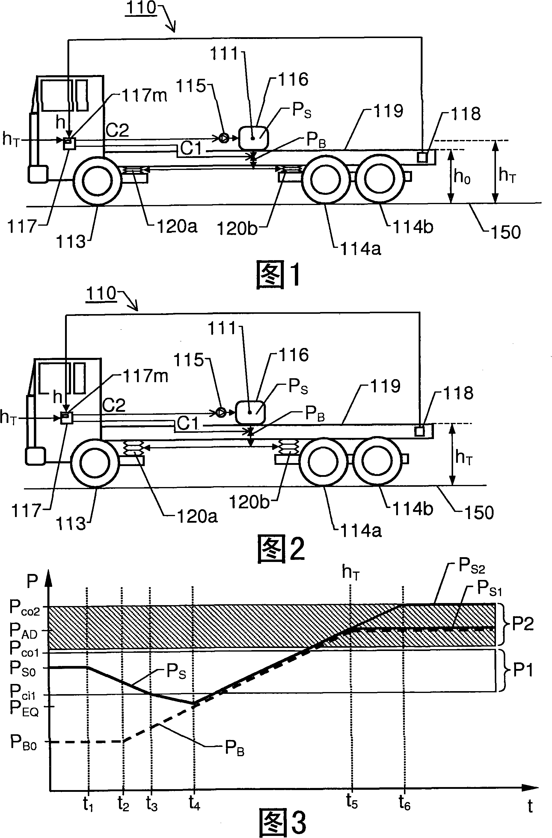
[0023] figure 1 A motor vehicle 110 such as a truck is shown according to one embodiment of the invention. The motor vehicle 110 has a chassis element 119 whose position relative to at least one pair of wheels 113 , 114 a and / or 114 b of the motor vehicle 110 can be changed. For this purpose, the motor vehicle 110 has a pneumatically operated control mechanism adapted to receive an input air flow and to influence the air flow between the chassis element 119 and at least one pair of wheels 113, 114a and / or 114b by varying the input air flow according to the first control signal C1. Positional relationship. For example, the pneumatically operated control mechanism device may include a plurality of bellows 120a and 120b, respectively, or an alternative type of gas container having at least one flexible wall adapted to output a mechanical force in response to a quantity of input gas.

[0024] The motor vehicle 110 also has, for example, a compressor 115 and a pressure tank 116 s...


PUM


Abstract

The present invention relates to automatic adjustment of a position relationship between a motor vehicle's (110) chassis element (119) and at least one wheel pair (113; 114a, 114b) of the vehicle (110). A control unit (117) receives a target value (hT) and a measured value (h) expressing the position relationship between the chassis element (119) and the at least one wheel pair (113; 114a, 114b). Based thereon, the control unit (117) produces a first control signal (C1), which influences an input air flow from a pneumatic pressure source system (115; 116) to a pneumatically operated control mechanism, such that the a position relationship is varied. The pressure source system (115; 116) produces a system pressure (PS), and a pressure sensor means (111) registers a pressure parameter indicative of the system pressure (PS). Furthermore, the control unit (117) compares the measured value (h) with the target value (hT), compares the system pressure (PS) with at least one pressure limit (Pco1; Pco2 ), investigates whether one of at least two decision criteria is fulfilled. Upon fulfillment of such a criteria, the control unit (117) controls the system pressure (PS) to a predefined level by means of a second control signal (C2). The predefined level depends on which decision criterion that is fulfilled.

Description

technical field [0001] The present invention generally relates to the automatic control of chassis components of motor vehicles. More particularly, the invention relates to a system according to the preamble of claim 1 and a motor vehicle according to claim 8 . The invention also relates to a method for adjusting the height of a chassis element of a motor vehicle according to the preamble of claim 9 , a computer program product according to claim 16 , and a computer-readable medium according to claim 17 . Background technique [0002] In heavy vehicles with pneumatic suspension systems, such as trucks, buses and tractors, it is often preferred to provide the possibility of adjusting the pressure level in the suspension system. That is, varying load levels and load distributions can be compensated for. In general, the accumulation of pneumatic pressure is related to energy consumption, and in order to save the fuel resources of the motor vehicle, the clever use of the compr...

Claims


Application Information

Patent Timeline
IPC IPC(8): B60G17/015
CPCB60G2400/252B60G17/0155F04B49/065B60G2202/152B60G2400/51222B60G17/018B60G2300/02
Inventor R·斯文松
Owner SCANIA CV AB
Why Eureka
Try Eureka