Element for generating a magnetic field

A technology for components and magnetic fields, applied in the field of components that generate magnetic fields, can solve problems such as taking a long time

Inactive Publication Date: 2009-08-26
CONTINENTAL AUTOMOTIVE GMBH
View PDF1 Cites 2 Cited by
  • Summary
  • Abstract
  • Description
  • Claims
  • Application Information

AI Technical Summary

Problems solved by technology

The disadvantage is that the adhesive needs to be out-gassed and takes a long time to harden completely

Method used


Image

  • Element for generating a magnetic field
  • Element for generating a magnetic field
  • Element for generating a magnetic field

Examples


Embodiment Construction

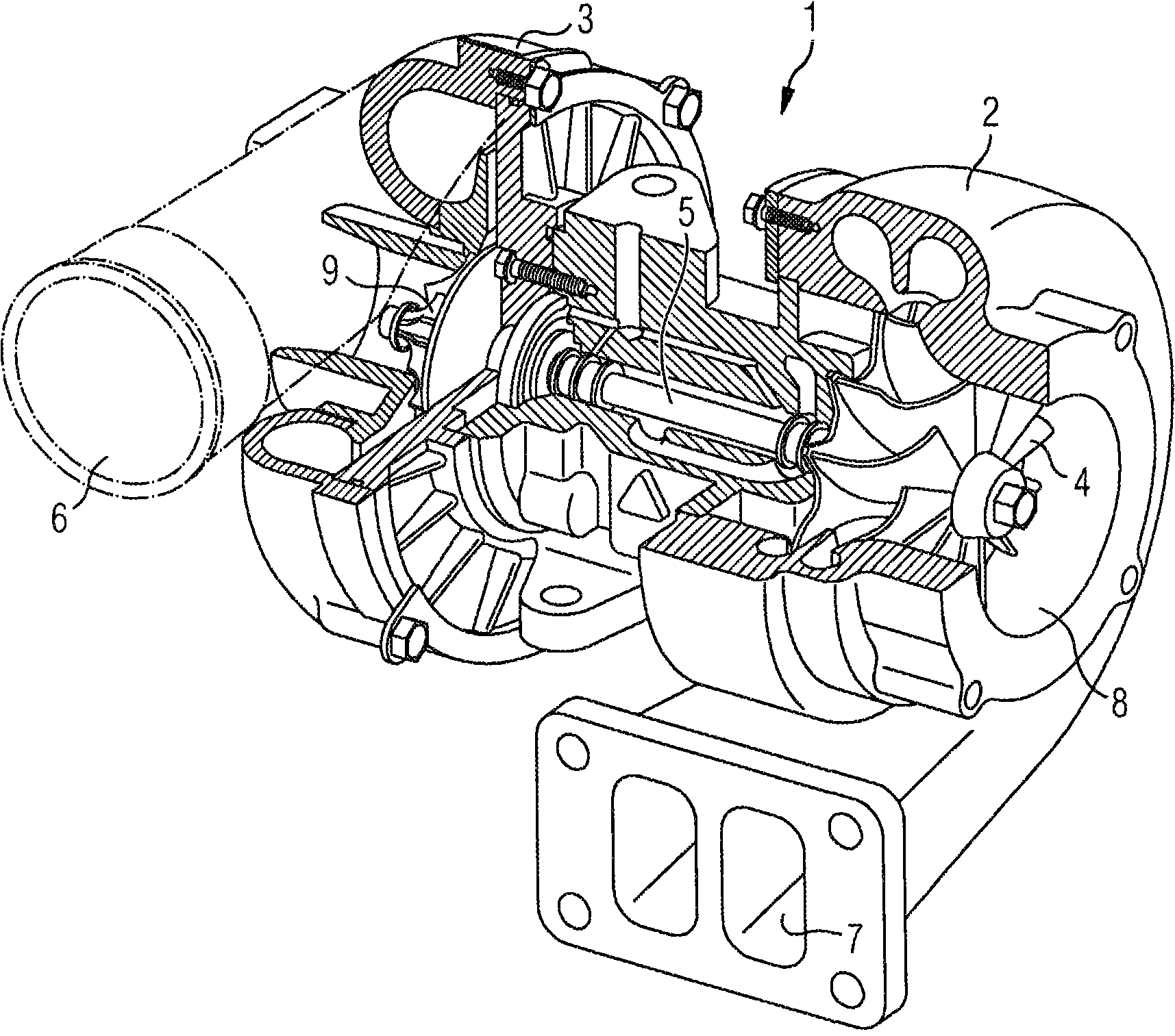
[0020] figure 1 An exhaust gas turbocharger 1 with a turbine 2 and a compressor 3 is shown. The compressor wheel 9 is rotatably mounted in the compressor 3 and connected to the turbine shaft 5 . The turbine shaft 5 is also mounted rotatably and is connected at its other end to the turbine wheel 4 . The combination of the compressor wheel 9 , the turbine shaft 5 and the turbine wheel 4 is also referred to as a rotor assembly. Hot exhaust gases from an internal combustion engine (not shown here) are discharged into the turbine 2 via the turbine inlet 7 , wherein the turbine wheel 4 is in rotation. The exhaust gas flow leaves the turbine 2 through the turbine outlet 8 . The turbine wheel 4 is connected to a compressor wheel 9 via a turbine shaft 5 . The turbine 2 thus drives the compressor 3 . In the compressor 3 , air is sucked in via the air inlet 16 , subsequently compressed in the compressor 3 and delivered to the internal combustion engine via the air outlet 6 .

[002...


PUM


Abstract

The invention relates to an element for generating a magnetic field, having an annular frame for receiving an annular magnet which rotates with a turboshaft, wherein the magnet is mounted in the frame in such a way that the frame stabilizes and guides the magnet mechanically. In order to specify an element for generating a magnetic field which reliably fixes and guides the magnet, the magnet is connected to the frame by at least one spot weld.

Description

technical field [0001] The invention relates to a component for generating a magnetic field having an annular frame for receiving an annular magnet rotating with a turbine shaft, wherein the magnet is arranged in the frame in such a way that the frame mechanically stabilizes and guides the magnet . Background technique [0002] A frequently used technical means for increasing the power of internal combustion engines is supercharging. The precompression of the combustion air is therefore carried out via the exhaust gas turbocharger or also by means of a compressor driven mechanically by the engine. An exhaust gas turbocharger basically consists of a compressor and a turbine, which are connected to a common shaft and rotate at the same speed. The turbine converts the normally useless exhaust energy of the deflagration into rotational energy and drives the compressor. A compressor, also referred to herein as a compressor, draws in fresh air and delivers precompressed air to ...

Claims


Application Information

Patent Timeline
Patent Type & Authority Applications(China)
IPC IPC(8): F02B39/16F01D17/06G01P3/44
CPCF05D2230/234F05B2270/304F05D2220/40F05B2220/40G01P3/487F05B2230/234F02B39/16F01D17/06F05D2270/304
Inventor 约翰内斯·安特马库斯·吉尔希斯特凡·海因里希安德烈亚斯·奥特
Owner CONTINENTAL AUTOMOTIVE GMBH
Why Eureka
Try Eureka