Energy storage module

A technology for energy storage modules and storage components, which is used in the manufacture of final products, electrolytic capacitors, multiple hybrid/electric double layer capacitors, etc., and can solve the problem that the system cannot be placed in the

Inactive Publication Date: 2009-08-26
SIEMENS AG
View PDF4 Cites 1 Cited by
  • Summary
  • Abstract
  • Description
  • Claims
  • Application Information

AI Technical Summary

Problems solved by technology

[0005] The latter means that the described system cannot usually be placed in a functionally favorable position for it

Method used


Image

  • Energy storage module

Examples


Embodiment Construction

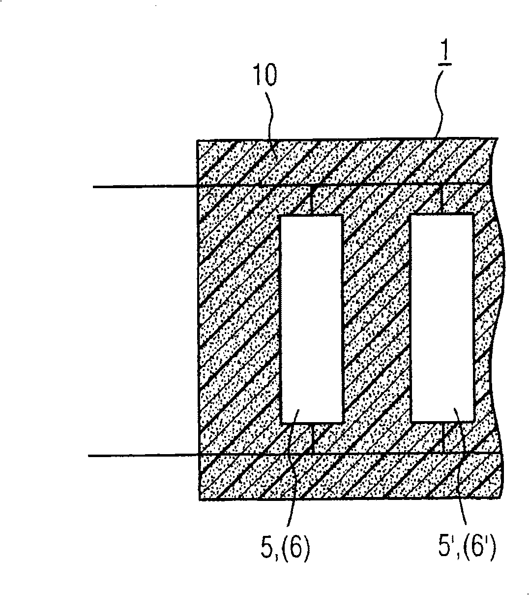
[0017] exist figure 1 An energy storage module is shown in , which is mainly composed of an outer casing 1 that is hermetically closed. In the module housing 1 a plurality of capacitors are connected in succession as individual electrolyzers, which capacitors are implemented as energy stores for certain applications in industrial plants, in particular also in passenger vehicles. In particular double layer capacitors 5 are considered as capacitors. As an alternative to this, known electrolytic capacitors 6 can also be used. exist figure 1 Special double layer capacitors 5, 5', 5", . . . are shown in .

[0018] The double-layer capacitor 5 or electrolytic capacitor 6 used uses a combustible organic electrolyte, respectively. In the event of a fault, combustion, explosion or at least deflagration can take place here. Appropriate security measures must be taken for this purpose. This measure should satisfy the principle of intrinsic safety, ie no other functional elements sh...


PUM

PropertyMeasurementUnit
Bulk densityaaaaaaaaaa

Abstract

Energy storage modules generally comprise a housing with component parts (5, 5', 6, 6') arranged therein. The component parts (5, 5', 6, 6') are in this case either capacitors, for example double-layer capacitors and / or electrolyte capacitors. According to the invention, a filler (10) is provided in the housing and binds electrolyte liquid occurring in the event of damage or else electrolyte gases. Beds of material with a large specific surface area, such as zeolites or else active carbons, are suitable as fillers (10). The surfaces are also possibly catalytically coated.

Description

technical field [0001] The invention relates to an energy storage module according to the preamble of claim 1 . Background technique [0002] Energy storage modules are known from the prior art, see for example the applicant's unpublished German patent application DE 10 2005 041 604 A1 entitled "Vorrichtung mit wenigstens einem Doppelschichtkondensator (device with at least one double-layer capacitor)". Such energy storage modules include a housing and components arranged therein, such as capacitors with a combustible organic electrolyte therein. Such electrolytes can cause explosions or deflagration under unfavorable boundary conditions. [0003] In capacitors, in particular double-layer capacitors, but also in electrolytic capacitors and lithium batteries, mainly organic electrolytes are used, which in the event of a fault or damage have a potential fire or even explosion hazard in the event of spillage. Sometimes the organic electrolyte also has a low vapor pressure. I...

Claims


Application Information

Patent Timeline
IPC IPC(8): H01G9/00H01G9/155
CPCH01G9/00H01G9/155Y02E60/13Y02P70/50H01G9/0003H01G9/08H01G9/14H01G11/10H01G11/80H01G11/82H01G11/14
Inventor 汉斯·H·埃布林沃尔特·埃尔哈特安德烈亚斯·富克斯马库斯·M·高登兹亚历山大·哈恩阿明·凯斯勒约肯·纽茨卡斯滕·雷肯伯格曼弗雷德·威德哈斯
Owner SIEMENS AG
Why Eureka
Try Eureka