Thin film magnetic sensor
A magnetic sensor and thin-film technology, applied in the field of thin-film magnetic sensors, can solve the problems of difficult magnetic field measurement and low magnetic field sensitivity
- Summary
- Abstract
- Description
- Claims
- Application Information
AI Technical Summary
Problems solved by technology
Method used
Image
Examples
Embodiment 1
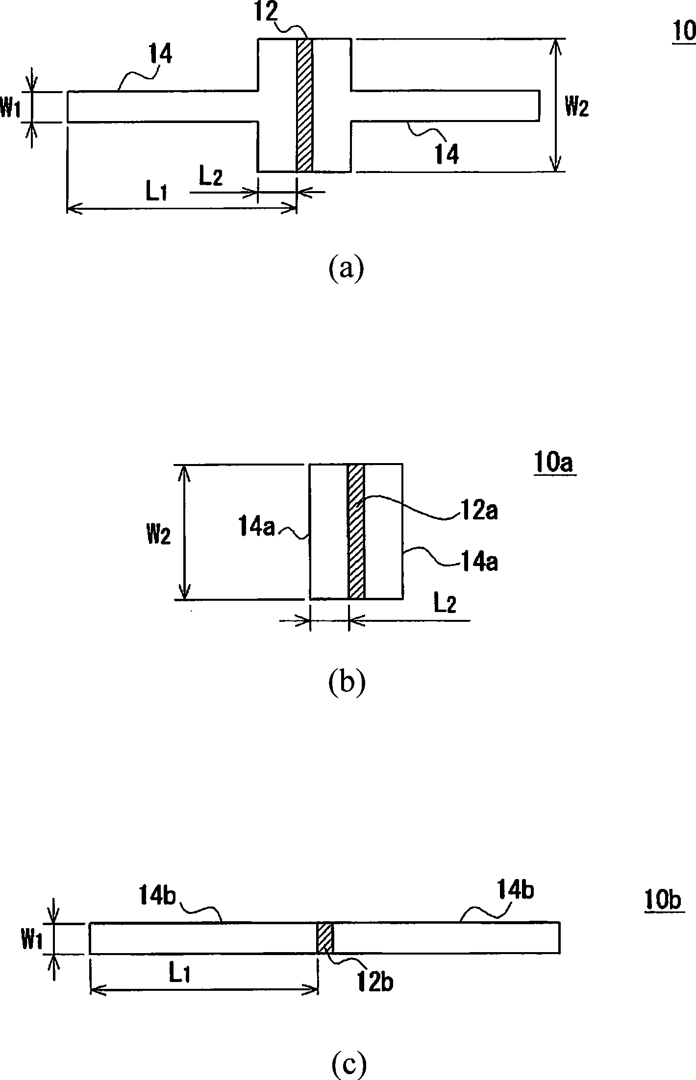
[0101] manufacture figure 1 The thin film magnetic sensor 10 is shown, and the MR characteristics are evaluated. FeCo-MgF 2 Nanoparticle alloys are used for GMR films12, the (Co 94 Fe 6 ) 70 Si 15 B 15 Amorphous alloys are used for thin film yokes 14,14.
[0102] In addition, the dimension of each part of the film yoke 14, 14 is as follows.
[0103] Overall length L of film yoke 14, 14 1 ×Width W of the longitudinal bar 1 : 150 μm × 20 μm.
[0104] The length L of the transverse rod 2 ×Width W of lateral bar 2 : 20 μm × 150 μm.
[0105] Figure 4 The MR characteristics of the obtained thin film magnetic sensor are shown. From Figure 4 It can be seen that the slope of the low magnetic field region of |H|≤10(Oe) is large, and the slope of the high magnetic field region of |H|>10(Oe) is small. This indicates that a low-field magnetic region in a magnetic field can be measured with high precision and a high-field magnetic region in a magnetic field can be measured...
Embodiment 2
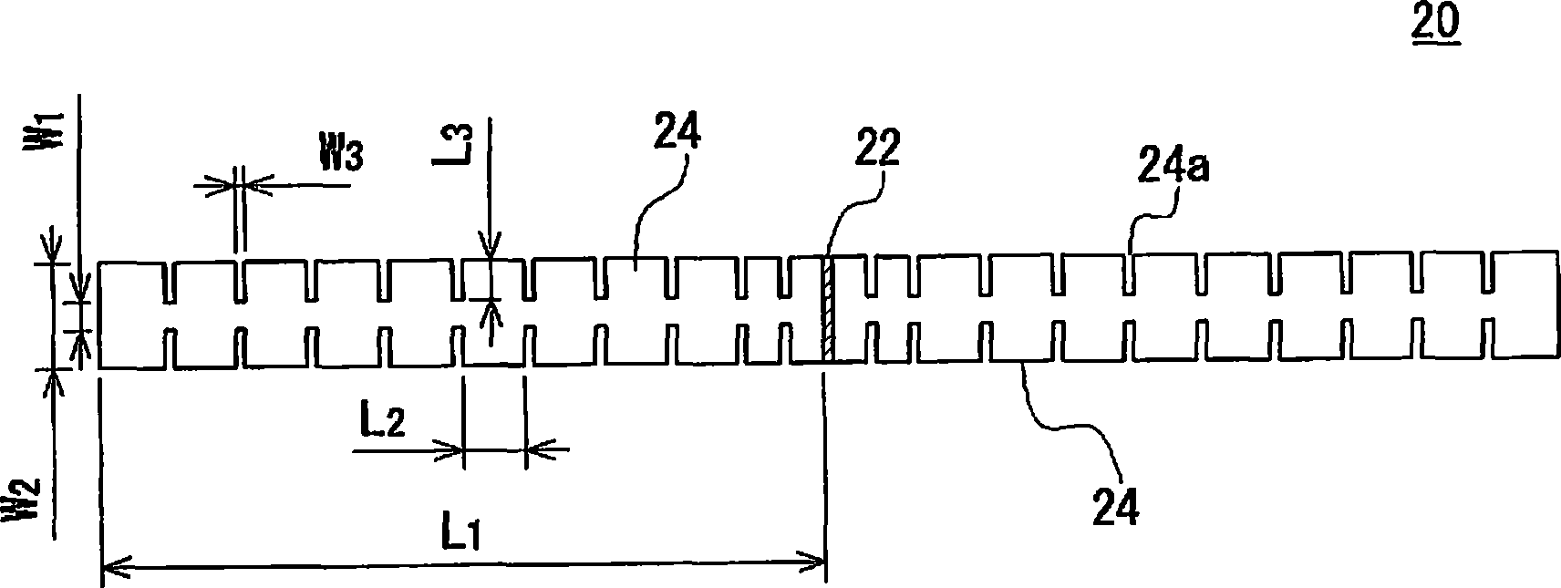
[0107] manufacture figure 2 The thin film magnetic sensor 20 is shown, and the MR characteristics are evaluated. FeCo-MgF 2 Nanoparticle alloys are used for GMR films22, the (Co 94 Fe 6 ) 70 Si 15 B 15 Amorphous alloys are used for thin film yokes 24,24.
[0108] In addition, the dimension of each part of the film yoke 24,24 is as follows.
[0109] Overall length L of film yoke 24, 24 1 ×Width W of the vertically long part 1 : 150 μm × 10 μm.
[0110] The length L of the horizontal long part 2 ×Width W of the horizontal long part 2 : 15 μm × 20 μm.
[0111] Cut length L 3 ×Slit width W 3 : 5 μm × 1 μm.
[0112] Figure 5 The MR characteristics of the obtained thin film magnetic sensor are shown. From Figure 5 It can be seen that the slope of the low magnetic field region of |H|≤5(Oe) is large, and the slope of the high magnetic field region of |H|>5(Oe) is small. This indicates that a low-field magnetic region in a magnetic field can be measured with high ...
Embodiment 3
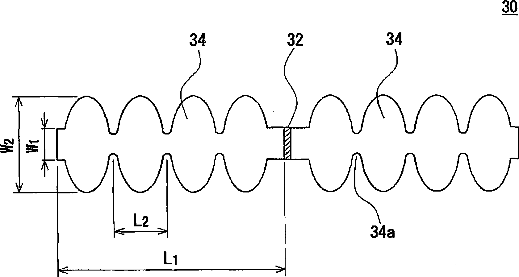
[0114] manufacture image 3 The thin film magnetic sensor 30 is shown, and the MR characteristics are evaluated. FeCo-MgF 2 Nanoparticle alloy is used for GMR film 32, the (Co 94 Fe 6 ) 70 Si 15 B 15 An amorphous alloy is used for the thin film yokes 34,34.
[0115] In addition, the dimension of each part of the film yoke 34,34 is as follows.
[0116] Overall length L of film yoke 34, 34 1 ×Width W of the vertically long part 1 : 150 μm × 20 μm.
[0117] The length L of the horizontal long part 2 ×Width W of the horizontal long part 2 : 40 μm × 100 μm.
[0118] Figure 6 The MR characteristics of the obtained thin film magnetic sensor are shown. From Figure 6 It can be seen that the slope of the low magnetic field region of |H|≤5(Oe) is large, and the slope of the high magnetic field region of |H|>5(Oe) is small. This indicates that a low magnetic field region in a magnetic field can be measured with high precision and a high magnetic field region in a magneti...
PUM
| Property | Measurement | Unit |
|---|---|---|
| thickness | aaaaa | aaaaa |
Abstract
Description
Claims
Application Information
 - R&D
- Intellectual Property
- Life Sciences
- Materials
- Tech Scout
- Unparalleled Data Quality
- Higher Quality Content
- 60% Fewer Hallucinations
Browse by: Latest US Patents, China's latest patents, Technical Efficacy Thesaurus, Application Domain, Technology Topic, Popular Technical Reports.
© 2025 PatSnap. All rights reserved.Legal|Privacy policy|Modern Slavery Act Transparency Statement|Sitemap|About US| Contact US: help@patsnap.com


