Broad beam navigation antenna adopting electromagnetic bandgap structure and novel installation method thereof

An electromagnetic bandgap structure and installation method technology, applied in the field of navigation antennas, can solve problems such as widening the antenna beam width, and achieve the effects of improving low elevation gain, low loss, and easy design and processing

Active Publication Date: 2009-09-02
BEIHANG UNIV
View PDF0 Cites 3 Cited by
  • Summary
  • Abstract
  • Description
  • Claims
  • Application Information

AI Technical Summary

Problems solved by technology

[0003] Find according to retrieval, most domestic and foreign scholars pay close attention to the design method of electromagnetic bandgap structure and characteristic research thereof at present, also do not see the report that combines research with electromagnetic bandgap structure design and installation method, the present invention combines electromagnetic bandgap structure and Combined with new installation methods, and applied to the design of navigation antennas, in order to achieve the purpose of widening the beam width of the antenna, to meet the needs of the new generation of satellite navigation

Method used

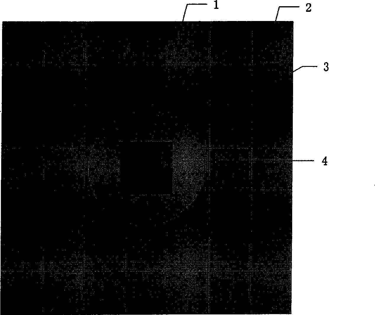

Image

  • Broad beam navigation antenna adopting electromagnetic bandgap structure and novel installation method thereof
  • Broad beam navigation antenna adopting electromagnetic bandgap structure and novel installation method thereof
  • Broad beam navigation antenna adopting electromagnetic bandgap structure and novel installation method thereof

Examples


Embodiment Construction

[0027] The present invention will be described in detail below in conjunction with the accompanying drawings and specific embodiments, but the scope of protection of the present invention is not limited to the following examples, but should include all content in the claims.

[0028] The present invention implements concrete steps as follows:

[0029] (1) Determine the parameters of the wide-beam navigation antenna according to the needs, including the operating frequency, VSWR, and gain indicators;

[0030] The parameters of the wide-beam navigation antenna can be determined according to user needs, including operating frequency, standing wave ratio, and gain index. In this embodiment, the operating frequency of the wide-beam navigation antenna is determined to be 1.575 GHz, the standing wave ratio is less than 1.5, and the gain of the 20-degree elevation angle is greater than -2dB, 5 degree elevation gain is greater than -5dB;

[0031] (2) Choose an ordinary circularly pola...


PUM


Abstract

The invention relates to a broad beam navigation antenna adopting an electromagnetic band-gap structure and a novel installation method thereof. The method comprises the following steps: firstly, the index parameters of the antenna, such as the working frequency, the standing wave ratio, the gaining, and the like are ensured, a common patch antenna is selected or designed, and the bottom of the common patch antenna is provided with a metal floor with a proper size as a supporting structure; the parameters of the electromagnetic band-gap structure are designed by using HFSS software according to know parameters, and the electromagnetic band-gap structure is made by adopting the prior technology; the center of the electromagnetic band-gap structure is cut into a circular area, and the electromagnetic band-gap structure is pasted on the surface of a metal floor and is solidified by a conductive adhesive so that the surface of the patch antenna is parallel to the surface of the electromagnetic band-gap structure, thereby a board beam navigation antenna which adopts electromagnetic band-gap structure and the novel installation method is completely designed. The antenna made by the invention is a low elevation angle and high gain antenna, the transmission of surface waves is restrained and the low elevation angle gain of the antenna is increased by adopting the electromagnetic bandgap structure and the novel installation method thereof.

Description

technical field [0001] The invention relates to a navigation antenna with excellent performance at low elevation angles, in particular to a navigation antenna with high gain at low elevation angles using an electromagnetic bandgap structure and a new installation method thereof. technical background [0002] The wide-beam navigation antenna is an antenna mainly used for receiving satellite navigation signals. It maintains good coverage in the range of 0° to 360° and elevation angle of 5° to 90°, but obtaining high power gain and circular polarization performance in the entire range of elevation angle of 5° to 90° is a difficult problem in antenna design. The feeding structure of ordinary patch antenna is simple, but affected by the surface wave, the low elevation angle gain is not high, and it is difficult to meet the requirements of satellite navigation. The electromagnetic bandgap structure is an artificial periodic structure with obvious frequency band gap characteristic...

Claims


Application Information

Patent Timeline
Patent Type & Authority Applications(China)
IPC IPC(8): H01Q1/38H01Q13/08
Inventor 张岩吕善伟张军张英锋
Owner BEIHANG UNIV
Why Eureka
Try Eureka