
Antenna phase-shift system

A phase shifting and antenna technology, applied in the field of antenna phase shifting system, can solve the problems that cannot be directly applied, and achieve the effect of simple implementation, compact overall structure and precise adjustment

Active Publication Date: 2013-05-22
COMBA TELECOM TECH (GUANGZHOU) CO LTD +1
View PDF2 Cites 0 Cited by
  • Summary
  • Abstract
  • Description
  • Claims
  • Application Information

AI Technical Summary

Problems solved by technology

[0006] For example, please refer to the CN2812316 patent announcement published on August 30, 2006, an adjustment device for mobile communication antenna phase shifters. Obviously, this adjustment device only performs phase shift for a row of radiation oscillators, and cannot be directly applied In the phasing process of multiple groups of beamforming networks in the TD-SCDMA smart antenna referred to in the present invention

Method used


Image

  • Antenna phase-shift system
  • Antenna phase-shift system
  • Antenna phase-shift system

Examples


Embodiment Construction

[0039] Below in conjunction with accompanying drawing and embodiment the present invention will be further described:

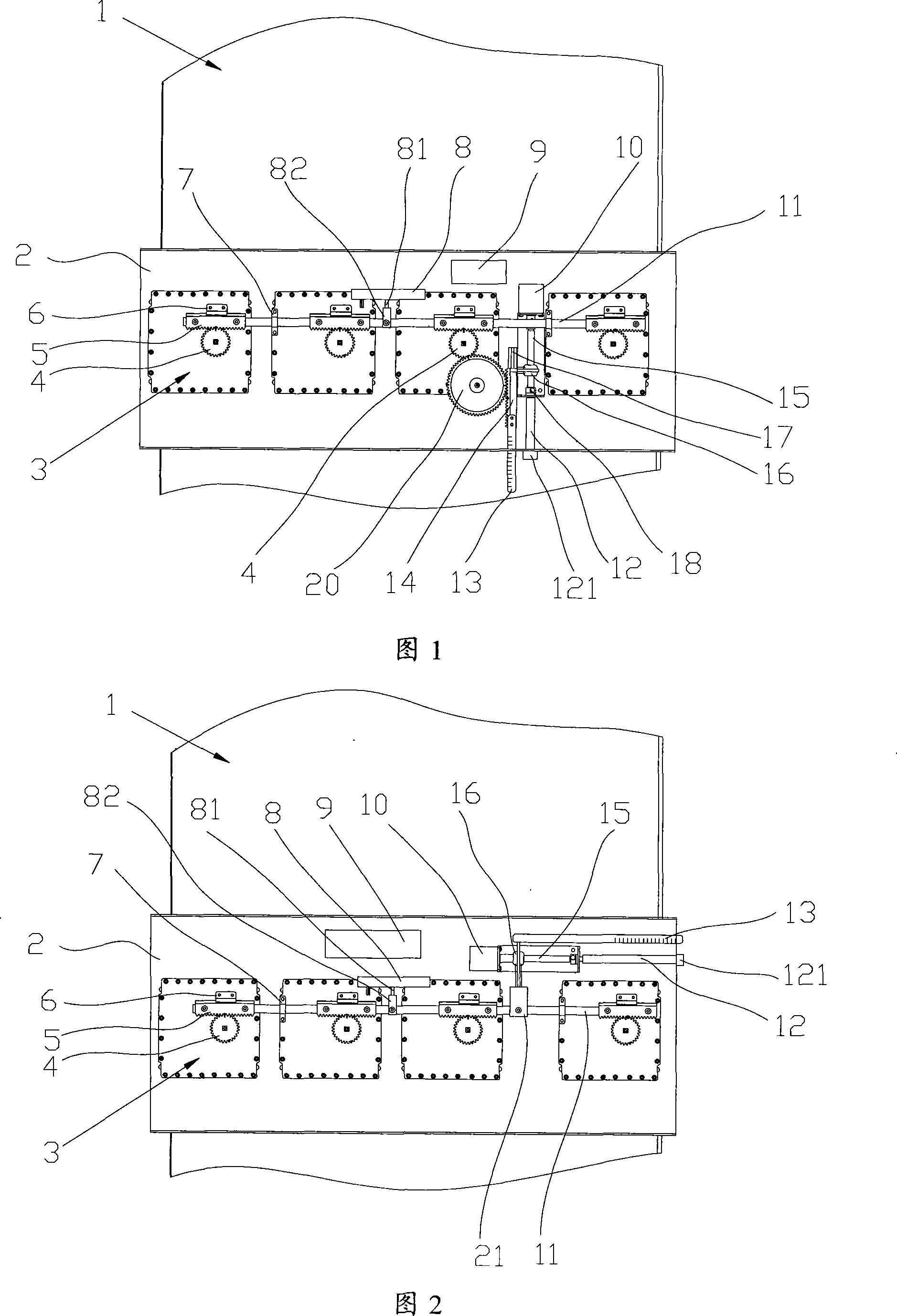
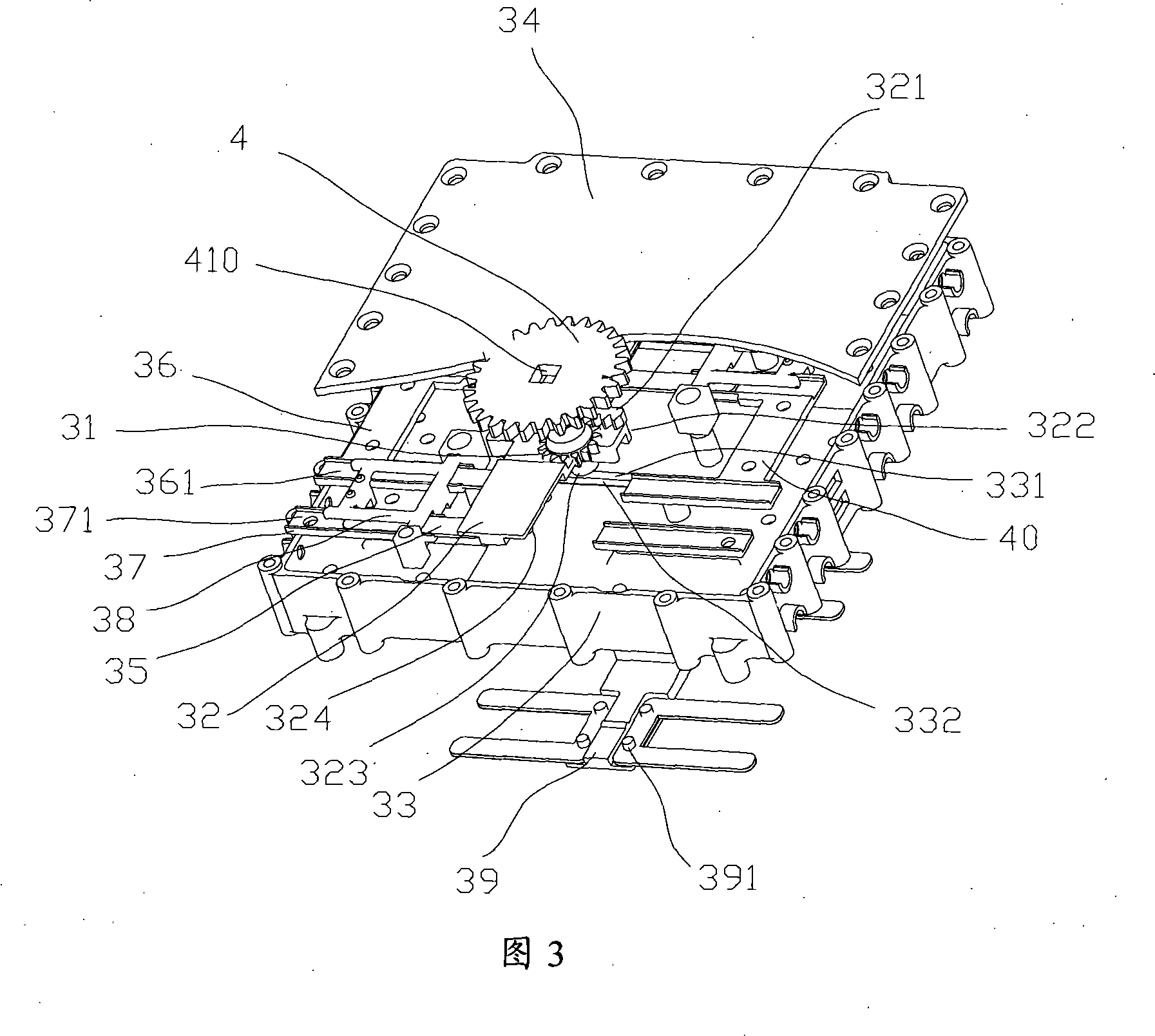
[0040] Please combine figure 1 and figure 2 , showing two embodiments of the present invention respectively, where figure 1 is a more preferred embodiment. The synchronous transmission device of the present invention, the beam forming network 3 and its associated mobile communication antenna 1 are shown in a front view. The synchronous transmission device of the present invention can be installed in the antenna encapsulation with the beam forming network 3, or can be installed in Inside the sealed box 2 outside the antenna encapsulation cover, those skilled in the art should know this modification. In order to simplify the description, in the examples listed in the present invention, the synchronous transmission device and the beamforming network 3 are all installed in a sealed box 2. In fact, the sealed box 2 can also be understood as a component of the ...


PUM


Abstract

The invention relates to an antenna phase-shift system, in particular to a simultaneous transmission device which accurately adjusts a plurality of groups of beam-forming networks in a multi-array antenna, a beam-forming network which is suitable for the antenna phase-shift system, and a precise phase-adjusting measurement and control device. The simultaneous transmitting device is used in an antenna which is provided with at least two radiating element arrays, implements control and realizes simultaneous phase shift to a phase-shift part which is owned by the beam-forming network of each radiating element array, comprising a driving device, a connecting rod and a transmission device, wherein the driving device is under the control of a control system which is independent of the antenna and provides a circular motion arm, the connecting rod is flexibly connected with the phase-shift part of each beam-forming network and causes each beam-forming network to shift the phase in a linking way under the linear motion of the connecting rod, and the transmission device converts the circular motion arm of the driving device into the linear motion of the connecting rod. The whole antenna phase-shift system has compact structure and can realize simultaneous precise phase adjustment to the antenna, in particular to TD-SCDMA antenna.

Description

【Technical field】 [0001] The invention relates to an antenna phase shifting system, in particular to a synchronous transmission device for accurately adjusting multiple groups of beamforming networks in a multi-array antenna, a beamforming network adapted to the phase shifting system of the present invention, and a precise phase modulation Measurement and control device. 【technical background】 [0002] As we all know, the antenna of a mobile communication base station is usually tilted downward at a certain angle relative to the horizontal line, which is called the antenna downtilt or depression angle. Adjusting the downtilt angle will directly affect the radiation effect of the base station. At present, two methods are mainly used to adjust the downtilt angle of the base station antenna. One way is to tilt down a certain physical angle when the antenna is installed, which is the so-called mechanical downtilt angle. The phase of the antenna can deflect the beam direction of...

Claims


Application Information

Patent Timeline
Patent Type & Authority Patents(China)
IPC IPC(8): H01Q3/30H01Q3/32H01Q3/36H01P1/18
Inventor 段红彬郭建江
Owner COMBA TELECOM TECH (GUANGZHOU) CO LTD
Learn More