Electric generator and electric bicycle using same

A technology of electric bicycles and generators, applied in the field of transportation, can solve the problems of increased driving torque and energy loss in intermediate links, and achieve the effects of reducing driving torque, eliminating pollution, and reducing gears

Inactive Publication Date: 2012-07-11
荆其林
View PDF0 Cites 0 Cited by
  • Summary
  • Abstract
  • Description
  • Claims
  • Application Information

AI Technical Summary

Problems solved by technology

In this way, the generator needs to pass through the driving mechanism of the multi-stage speed-up gear, the driving torque increases, and the energy loss of the intermediate link is also increased.

Method used


Image

  • Electric generator and electric bicycle using same
  • Electric generator and electric bicycle using same
  • Electric generator and electric bicycle using same

Examples


Embodiment Construction

[0021] The generator according to the present invention and the electric bicycle using the generator will be further described in detail below in conjunction with the accompanying drawings and specific embodiments.

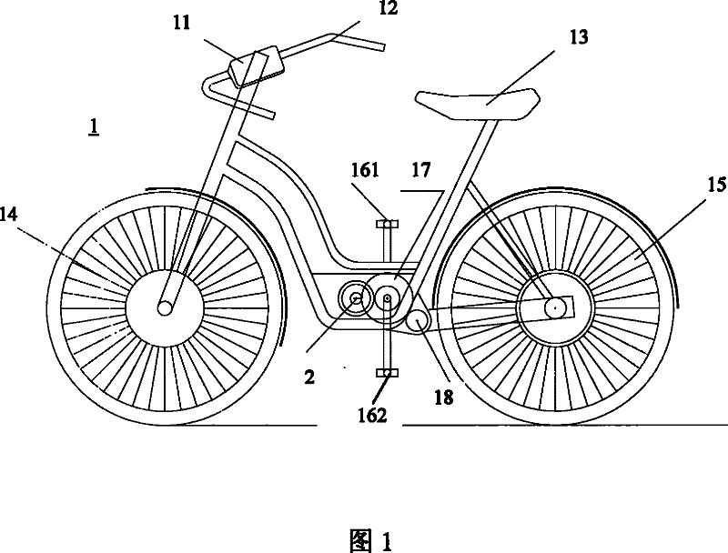
[0022] Such as figure 1 Shown, the electric bicycle 1 of a preferred embodiment of the present invention has front wheel 14, rear wheel 15, the direction controller 12 that connects front wheel 14, vehicle seat 13, pedal 161,162, double input gear 17, hinge 18. Composite combined rotor generator 2. The composite combined rotor generator 2 is located in the middle of the bicycle 1, and is located in the housing 20 with the motor (not shown in the figure), and is connected with the gears acting on the pedals 161, 162, and the connection method is not limited.

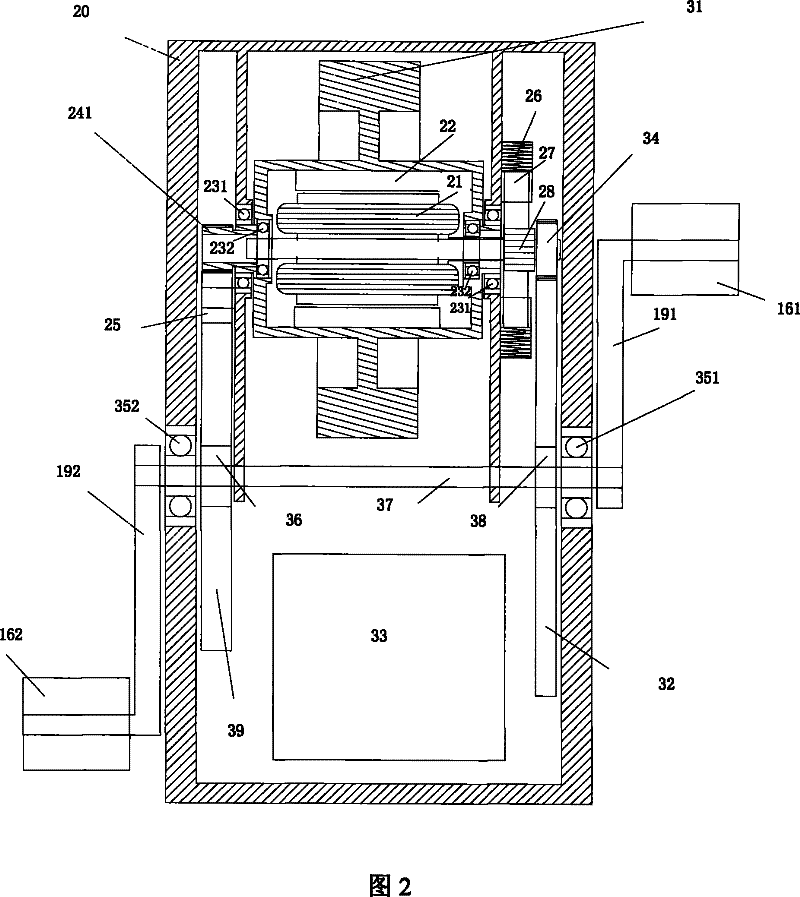
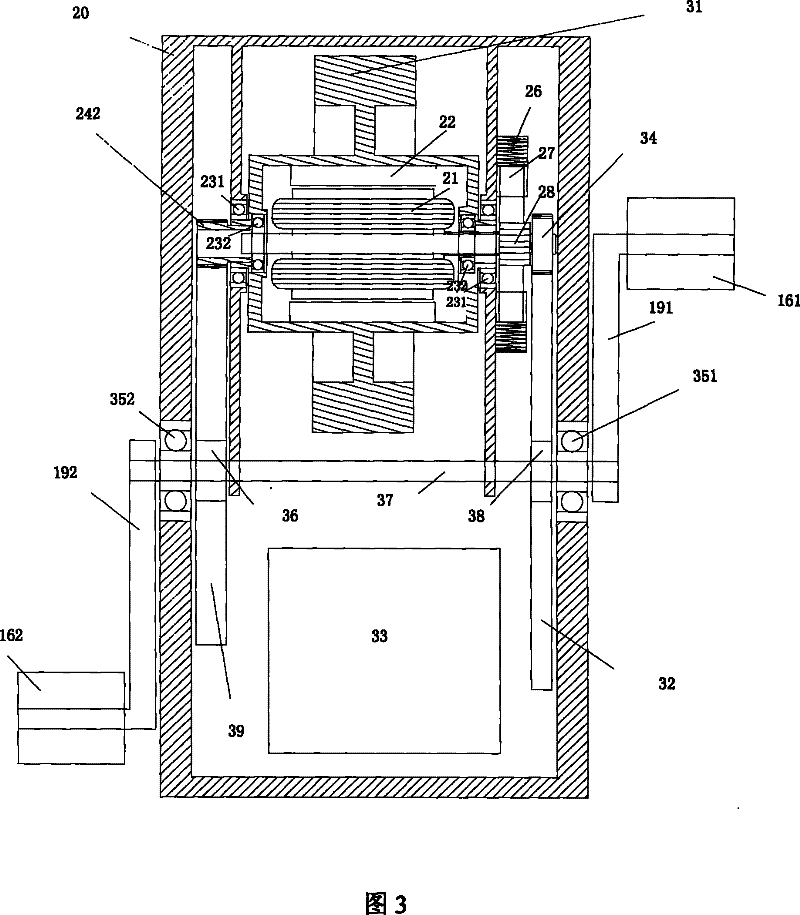
[0023] The generator of a preferred embodiment of the present invention is as figure 2 , Figure 4A , shown in 4B, includes the housing 20, and there are two driving gears 39, 32 in the housing 20 which a...


PUM


Abstract

The invention provides an electric generator and an electric bicycle using same; wherein the electric generator comprises a shell fixed on a bicycle frame, an outer rotor arranged inside the shell, anThe invention provides an electric generator and an electric bicycle using same; wherein the electric generator comprises a shell fixed on a bicycle frame, an outer rotor arranged inside the shell, and an inner rotor arranged inside the outer rotor; the shell has two drive gears that are rotatablely connected with a crank transmission shaft of the bicycle inside, wherein the outer rotor drive geard an inner rotor arranged inside the outer rotor; the shell has two drive gears that are rotatablely connected with a crank transmission shaft of the bicycle inside, wherein the outer rotor drive gear drives the rotation of the outer rotor through an outer rotor actuating mechanism, and the inner rotor drive gear drives the rotation of the inner rotor in a relatively opposite direction of the outedrives the rotation of the outer rotor through an outer rotor actuating mechanism, and the inner rotor drive gear drives the rotation of the inner rotor in a relatively opposite direction of the outer rotor rotation direction through an inner rotor actuating mechanism, thus leading the outer rotor and the inner rotor to rotate in relatively opposite direction; and electricity generated by the eler rotor rotation direction through an inner rotor actuating mechanism, thus leading the outer rotor and the inner rotor to rotate in relatively opposite direction; and electricity generated by the electric generator is transmitted to an electric motor through a circuit, and the electric motor drives the bicycle to advance. Under the magnetic flux-invariable situation, the drive moment and the drivctric generator is transmitted to an electric motor through a circuit, and the electric motor drives the bicycle to advance. Under the magnetic flux-invariable situation, the drive moment and the drive speed of the electric generator are correspondingly lowered, thus leading riders to consume less physical strength and avoiding the usage of storage batteries.e speed of the electric generator are correspondingly lowered, thus leading riders to consume less physical strength and avoiding the usage of storage batteries.

Description

technical field [0001] The invention relates to the technical field of vehicles, in particular to a generator and an electric bicycle using the generator. Background technique [0002] With the continuous improvement of living standards and quality, people pay more attention to the quality of life and work efficiency while enjoying the dazzling and colorful life. Professional vocabulary such as atmospheric environmental quality, carbon dioxide and greenhouse gas emissions has become the mantra of the common people. Therefore, it is conceivable that people's emphasis on the quality of life has been "not what it used to be". In addition, with the continuous updating of transportation tools, the work efficiency has also been significantly improved, and the radius of people's activities has continued to expand, thereby promoting the rapid improvement of people's information volume and quality of life. [0003] As we all know, the use of modern vehicles and vehicles is developi...

Claims


Application Information

Patent Timeline
Patent Type & Authority Patents(China)
IPC IPC(8): H02K16/00H02K21/00F03G5/06B60L11/02B60L11/08B60L50/10B60L50/13
CPCY02T10/7077Y02T10/641Y02T10/64Y02T10/7072
Inventor 荆其林何英杰刘敏刘贵军荆涛戴天耀张晋嘉
Owner 荆其林
Why Eureka
Try Eureka