Tubular shaft instrument

A technology for tube shafts and instruments, applied in endoscopic cutting instruments, parts of surgical instruments, medical science, etc., can solve problems such as fast tool wear

Active Publication Date: 2009-09-02
ERBE ELEKTROMEDIZIN GMBH
View PDF5 Cites 688 Cited by
  • Summary
  • Abstract
  • Description
  • Claims
  • Application Information

AI Technical Summary

Problems solved by technology

Rapid knife wear as the blade or knife rests on the tissue at only one point

Method used


Image

  • Tubular shaft instrument
  • Tubular shaft instrument
  • Tubular shaft instrument

Examples


Embodiment Construction

[0045] In the following description the same reference numerals are used for the same parts and parts functioning in the same way.

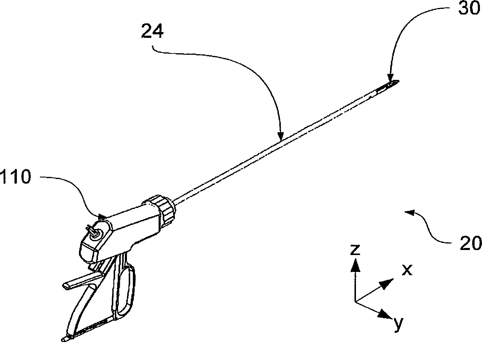
[0046] figure 1A general overview of an embodiment of a tubular shaft instrument according to the invention is provided. It shows three functional parts of the cannula instrument: the handle 110 , the slightly elongated cannula 24 , and the tool head 30 disposed on the distal end of the cannula 24 . The tool head 30 provides the actual function of the shaft instrument. The tool head is used to cut and / or coagulate tissue. The handle 110 controls the movement of the tool head 30 . Specifically, the mouthpiece 10, 10' (see figure 2 ) close and open to fix, coagulate, and cut tissue.

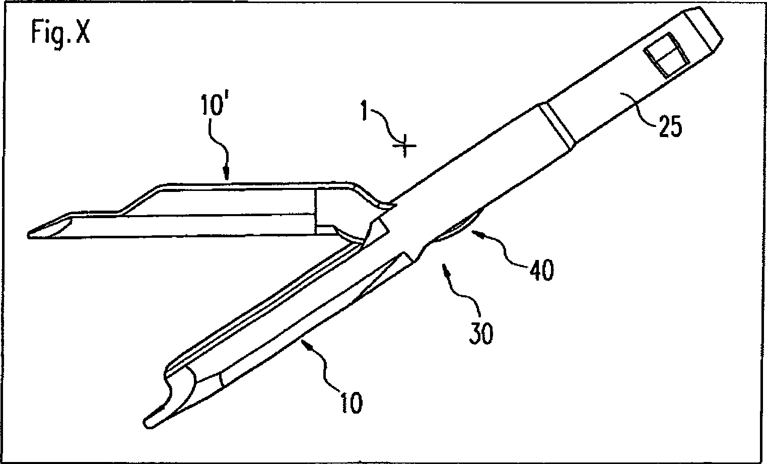
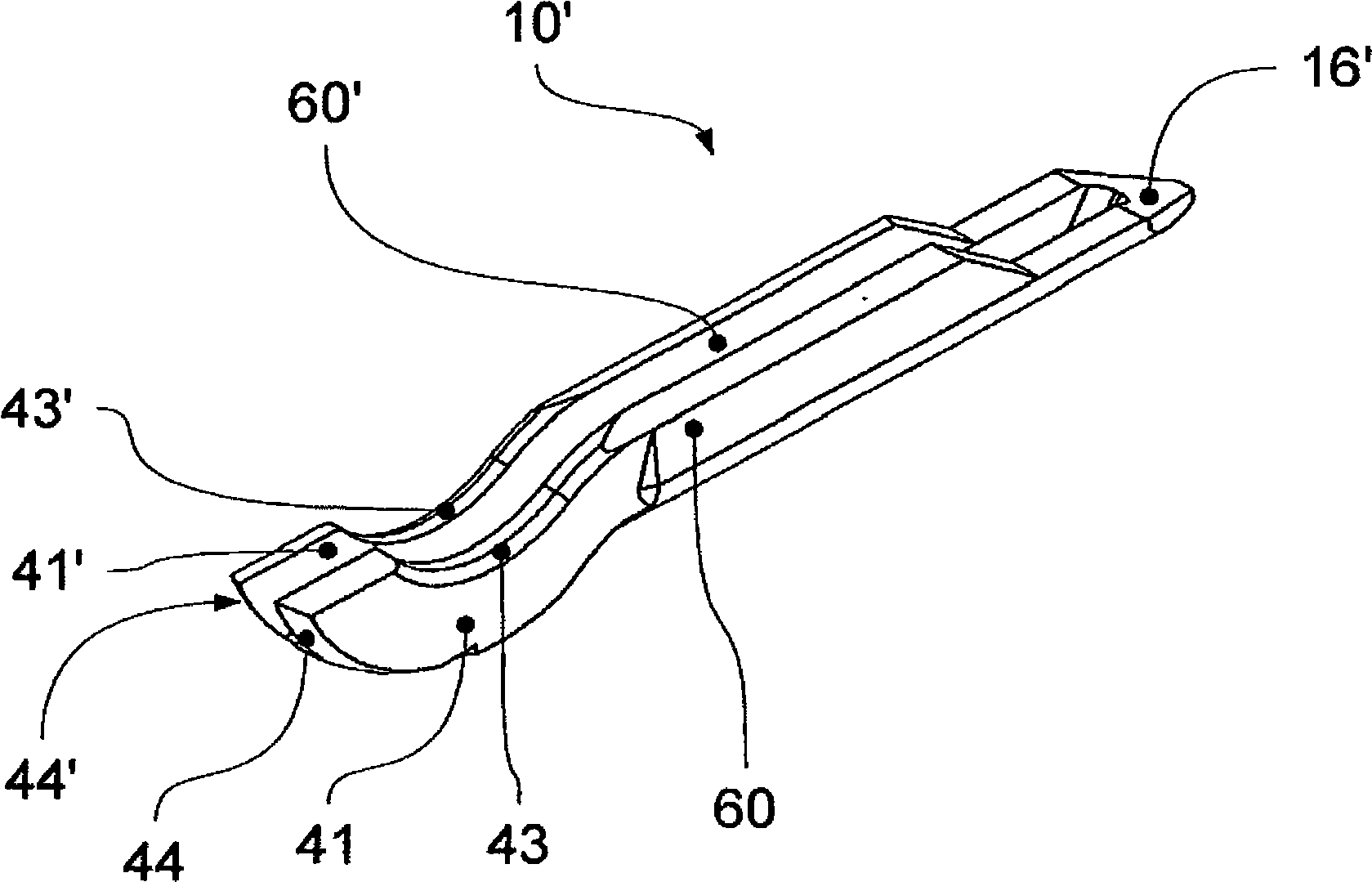
[0047] figure 2 An embodiment of a tool head 30 according to the invention is shown, comprising a first mouthpiece 10 and a second mouthpiece 10'. The first mouthpiece 10 is an ellipsoid having, on its side facing the tube axis 24 , an adapter 25 rigidly...


PUM


Abstract

The invention relates to a tubular shaft instrument for separating tissue. In conventional tubular shaft instruments the clean separation of tissue poses a problem. In practice, it is often the case that e.g. as a result of wear to the blade, the tissue is severed by the active force rather than by the action of the blade. The cut edges are also deformed accordingly. The invention relates to a tubular shaft instrument that guarantees a significantly more reliable, cleaner separation of tissue. To achieve this, in contrast to conventional cutting devices, the blade is not displaced through the fixed tissue, but glides over the latter until a complete separation is determined.

Description

technical field [0001] The invention relates to a tubular shaft instrument according to the preamble of claim 1 . Background technique [0002] In modern medicine, an attempt is generally made to keep damage to intact tissue to a minimum. Therefore, minimally invasive surgery is often the preferred method for surgical intervention when circumstances permit. The small incisions and minimal trauma to the tissue result in less postoperative pain and allow for quicker recovery and mobility. The same applies to laparoscopic surgery during complex procedures performed in the abdominal cavity. [0003] This type of surgery, and the instruments required for it, present special challenges to medical device manufacturers, since most surgical steps are performed in very confined spaces and without direct visual contact. The medical devices used must therefore not only be able to operate in the smallest of spaces but also must function so reliably that no visual monitoring is require...

Claims


Application Information

Patent Timeline
Patent Type & Authority Applications(China)
IPC IPC(8): A61B17/32
CPCA61B2017/07214A61B2017/320064A61B18/1447A61B2017/07285A61B17/320016A61B18/1482A61B2018/1457A61B17/3201A61B17/07207A61B2017/00473
Inventor 迪特尔·哈夫纳
Owner ERBE ELEKTROMEDIZIN GMBH
Why Eureka
Try Eureka