Device for sensing a fault current in a field bus system

A technology of fieldbus and fault current, applied in the direction of line fault/interference reduction, transmission system, baseband system components, etc., can solve the problem that the bus line cannot be reliably monitored for faults

Active Publication Date: 2009-09-02
ZF CV SYST EURO BV
View PDF2 Cites 21 Cited by
  • Summary
  • Abstract
  • Description
  • Claims
  • Application Information

AI Technical Summary

Problems solved by technology

This has the obvious disadvantage that bus lines which tend to oscillate due to a certain line length cannot be reliably monitored for faults

Method used


Image

  • Device for sensing a fault current in a field bus system
  • Device for sensing a fault current in a field bus system
  • Device for sensing a fault current in a field bus system

Examples


Embodiment Construction

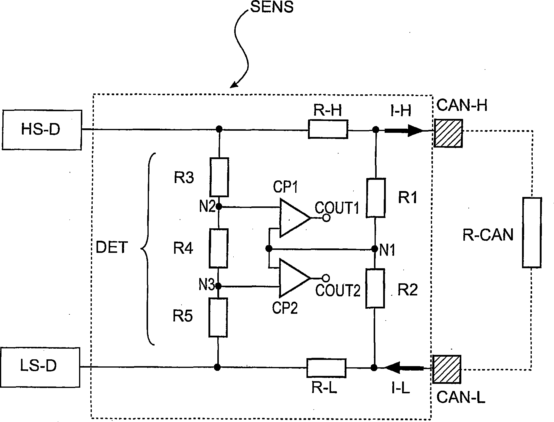
[0023] figure 1 A simplified circuit diagram of an embodiment according to an advantageous aspect of the invention is shown. The fault detection switching circuit SENS according to the invention is arranged between the two transmission lines CAN-H, CAN-L of the CAN bus system. In a typical CAN bus system a large number of two-wire transmission paths are provided, each with two transmission lines CAN-H, CAN-L. Line CAN-H is coupled to an output driver High-Side-Driver HS-D (High-Side-Driver). The output driver generates voltage levels and / or current levels according to standard specifications. The same applies to the transmission line CAN-L, which is coupled to a corresponding driver LS-D (Low-Side-Driver). Resistors R-H and R-L are coupled in lines CAN-H and CAN-L as first and second sensing means. Connected to these resistors is a detection device, namely a switching circuit DET for detecting a fault or for detecting a fault current. Via the voltage divider R1 / R2, the av...


PUM


Abstract

The invention relates to an electric switching circuit for operating a bus of a field bus system comprising means for sensing a fault current. Said means comprise first means for determining a first current of a first bus line, second means for determining a second current of a second bus line and means for detecting a fault based on the first current and the second current.

Description

technical field [0001] The invention relates to a switching circuit for detecting faults in a bus system and to a corresponding method. Background technique [0002] For communication between electronic controllers and for controlling and monitoring sensors and actuators in vehicles, bus systems such as the Controller-Area-Network (CAN), also referred to as CAN bus for short, are increasingly used today. In this case, a transmission of electrical signals is provided between the sending and receiving bus participants, which takes place via electronic lines. Such lines may be damaged during operation due to mechanical loads or other influences, which lead to failures during transmission. Damaged lines should no longer be used in bus systems, but conventional systems can only detect faults on bus system lines to a limited extent. A detected fault can therefore only be reacted to a limited extent (for example by disconnecting a damaged path). Conventional mechanisms for testi...

Claims


Application Information

Patent Timeline
Patent Type & Authority Applications(China)
IPC IPC(8): H04L25/08H04L69/40
CPCH04L25/08
Inventor 奥拉夫·阿伦斯于尔根·博德延斯·弗吕豪夫安德里亚斯·格斯
Owner ZF CV SYST EURO BV
Why Eureka
Try Eureka