Novel straight-shaft beating-up mechanism

A direct axis, new type of technology, applied in the direction of looms, textiles, textiles and papermaking, etc., can solve the problems of easy deformation, poor quality of cloth surface, short service life, etc. long effect

Inactive Publication Date: 2009-09-09
王勇
View PDF1 Cites 2 Cited by
  • Summary
  • Abstract
  • Description
  • Claims
  • Application Information

AI Technical Summary

Problems solved by technology

[0002] At present, the crank weft beating mechanism adopted by a large number of rapier looms in China is a copper tile combined with a handle with a sley to achieve beating. The copper tile drives the handle for sliding friction, which is easy to wear and cause gaps, which is not conducive to the quality control of the cloth surface. Easy to disengage during use, easy to deform when driving with high torque
For example, the patent No. 200610039399.X discloses a napping and beating-up mechanism of a towel rapier loom, which includes a four-link beating-up assembly consisting of a crankshaft, a crank, a handle and a sley foot, and the crankshaft is rotatably mounted on the frame Above, the right end of the handle is connected to the crank hinge, and the left end of the handle is fixed on the sley foot through bearing, eccentric cam, and handle bolt hinge connection, and the crankshaft rotates to drive the handle to move through the crank, thereby driving the eccentric cam fixed on the sley foot Rotation achieves weft beating, but its shortcomings are: there is sliding friction between the crank and the handle, and the loom is easy to wear when it runs for a long time, resulting in a weft beating gap, and the quality of the cloth surface is poor; the eccentric cam is installed on the sley foot. It is easy to deform when holding hands to transmit large torque, and it is not conducive to improving the beating speed, low applicability, low work efficiency, and short service life

Method used


Image

  • Novel straight-shaft beating-up mechanism

Examples


Embodiment Construction

[0008] The present invention will be further described below in conjunction with drawings and embodiments.

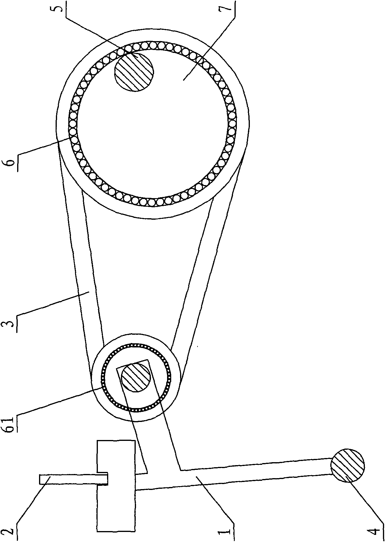
[0009] figure 1 The new straight-axis beating-up mechanism shown includes a sley assembly 1, a steel reed 2, a beating-up link 3, a pendulum shaft 4, and a beating-up shaft 5. The sley assembly 1 is connected to the pendulum shaft 4 and can rotate around the pendulum shaft. Sley assembly 1 is provided with steel reed 2, and eccentric cam 7 is fixed on the beat-up shaft 5, and eccentric cam 7 is connected to one end of beating-up link 3 through bearing 6, and the other end of beating-up link 3 is connected with bearing 61 and The sley assembly 1 is connected. When the loom is working, the rotation of the beating shaft 5 drives the eccentric cam 7 to rotate eccentrically, the eccentric cam 7 drives the beating link 3 through the bearing 6, and the beating link 3 drives the sley assembly 1 and the reed 2 through the bearing 61 to swing The shaft 4 rotates as a fulcrum, a...


PUM


Abstract

The invention relates to a novel straight-shaft beating-up mechanism comprising a sley component, a reed, a beating-up connecting rod, a swinging shaft and a beating-up shaft. The sley component is connected with the swinging shaft and is provided with the reed; the beating-up shaft is a straight shaft, and an eccentric cam is fixed on the beating-up shaft; the eccentric cam is connected with one end of the beating-up connecting rod via a bearing, and the other end of the beating-up connecting rod is connected with the sley component. The mechanism adopts the straight shaft to drive the sley component via the eccentric cam to beat up, has high beating-up precision, little wearing, large beating-up force, difficult deformation in large-torque transmission, long service life, no gap of beating-up and high cloth quality, is convenient for a weaving machine to accelerate and has high adaptability.

Description

technical field [0001] The invention relates to the field of textile machinery, in particular to a novel direct-axis beating-up mechanism with little wear and no gap. Background technique [0002] At present, the crank weft beating mechanism adopted by a large number of rapier looms in China is a copper tile combined with a handle with a sley to achieve beating. The copper tile drives the handle for sliding friction, which is easy to wear and cause gaps, which is not conducive to the quality control of the cloth surface. It is easy to get out of joint when using, and it is easy to deform when driving with high torque. For example, the patent No. 200610039399.X discloses a napping and beating-up mechanism of a towel rapier loom, which includes a four-link beating-up assembly consisting of a crankshaft, a crank, a handle and a sley foot, and the crankshaft is rotatably mounted on the frame Above, the right end of the handle is connected to the crank hinge, and the left end of...

Claims


Application Information

Patent Timeline
Patent Type & Authority Applications(China)
IPC IPC(8): D03D49/60D03D51/00
Inventor 王勇
Owner 王勇
Why Eureka
Try Eureka