Energy-saving and noise-reducing vacuum pump

A vacuum pump and noise reduction technology, which is applied in the direction of pumps, pump components, variable displacement pump components, etc., can solve the problems that it is difficult to ensure the concentricity, the operation of the vacuum pump is not stable, and the deflection angle α is easy to occur, so as to reduce vibration and noise , reduce volume, reduce the effect of assembly times

Inactive Publication Date: 2009-09-09
周纪昌
View PDF0 Cites 6 Cited by
  • Summary
  • Abstract
  • Description
  • Claims
  • Application Information

AI Technical Summary

Problems solved by technology

For example, the diaphragm type double pump chamber air circuit parallel vacuum pump, the motor and the vacuum pump chamber are fixedly connected by screws, which are mainly used in industrial equipment and household appliances. The work of the vacuum pump chamber is that the circular motion of the motor is transformed into a diaphragm through the eccentric wheel. Reciprocating motion, the shortcomings of the existing technology: first, because the vacuum pump assembly is repeated assembly, and the left and right pull rods 7', 8' are directly installed at both ends of the motor shaft, the assembled left pull rod 7' and right pull rod 8' are extremely It is prone to deflection angle α, such as Figure 4 As shown, that is, the phase of the two tie rods cannot reach 180° after assembly, and the precision is low, which makes the operation of the vacuum pump unstable; secondly, the pump cover and the motor casing of the existing vacuum pump are two independent shells. It is not easy to ensure the concentricity, and the assembly accuracy is low
Household appliances require that the noise of the product be below 45 decibels, and existing products cannot meet the requirements.
In addition, the heat dissipation system of the existing vacuum pump is to install fans separately on the motor shaft end cover. The fans need to lay additional circuits and energy, which is large in size and consumes a lot of energy.

Method used


Image

  • Energy-saving and noise-reducing vacuum pump
  • Energy-saving and noise-reducing vacuum pump
  • Energy-saving and noise-reducing vacuum pump

Examples


Embodiment Construction

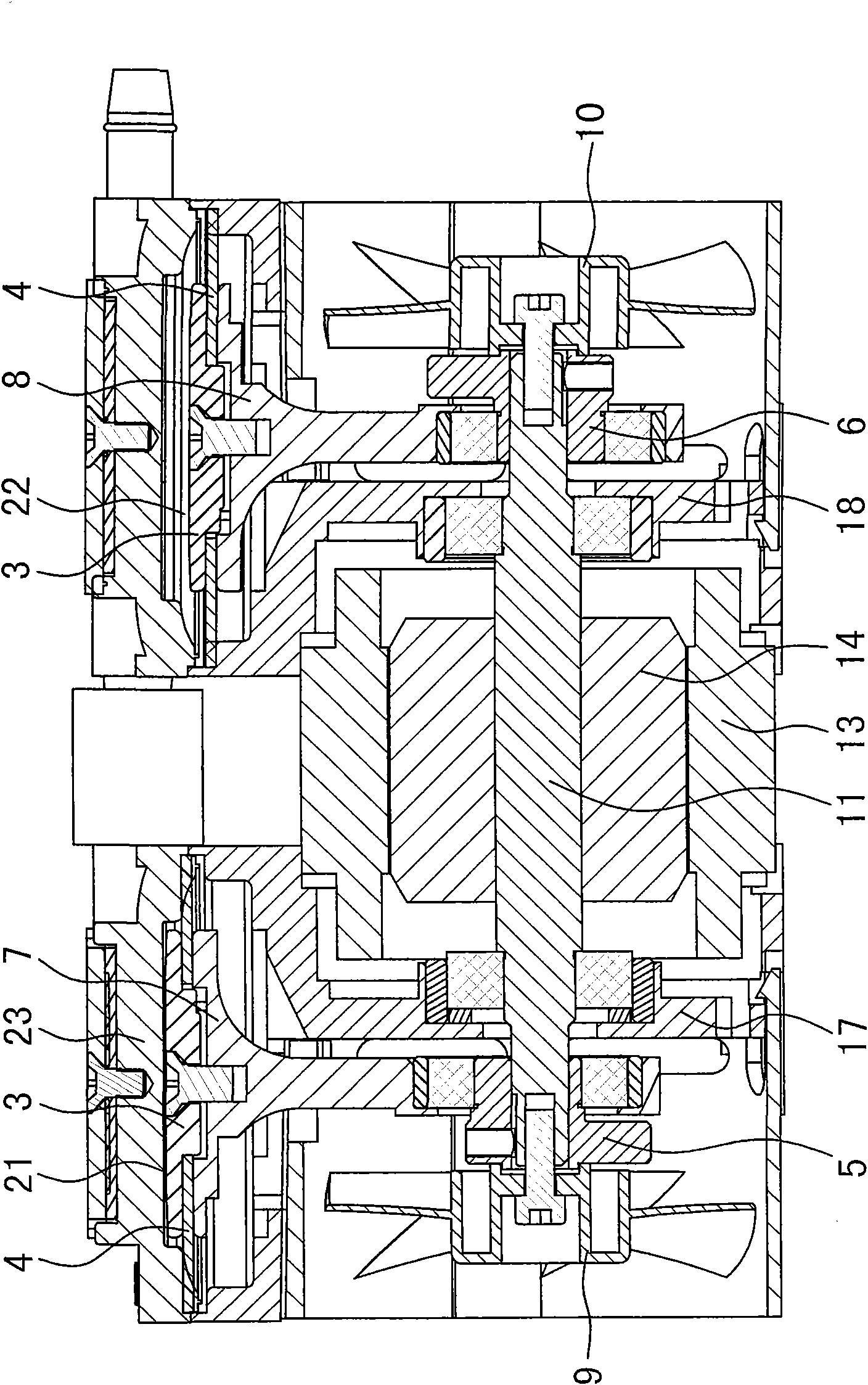
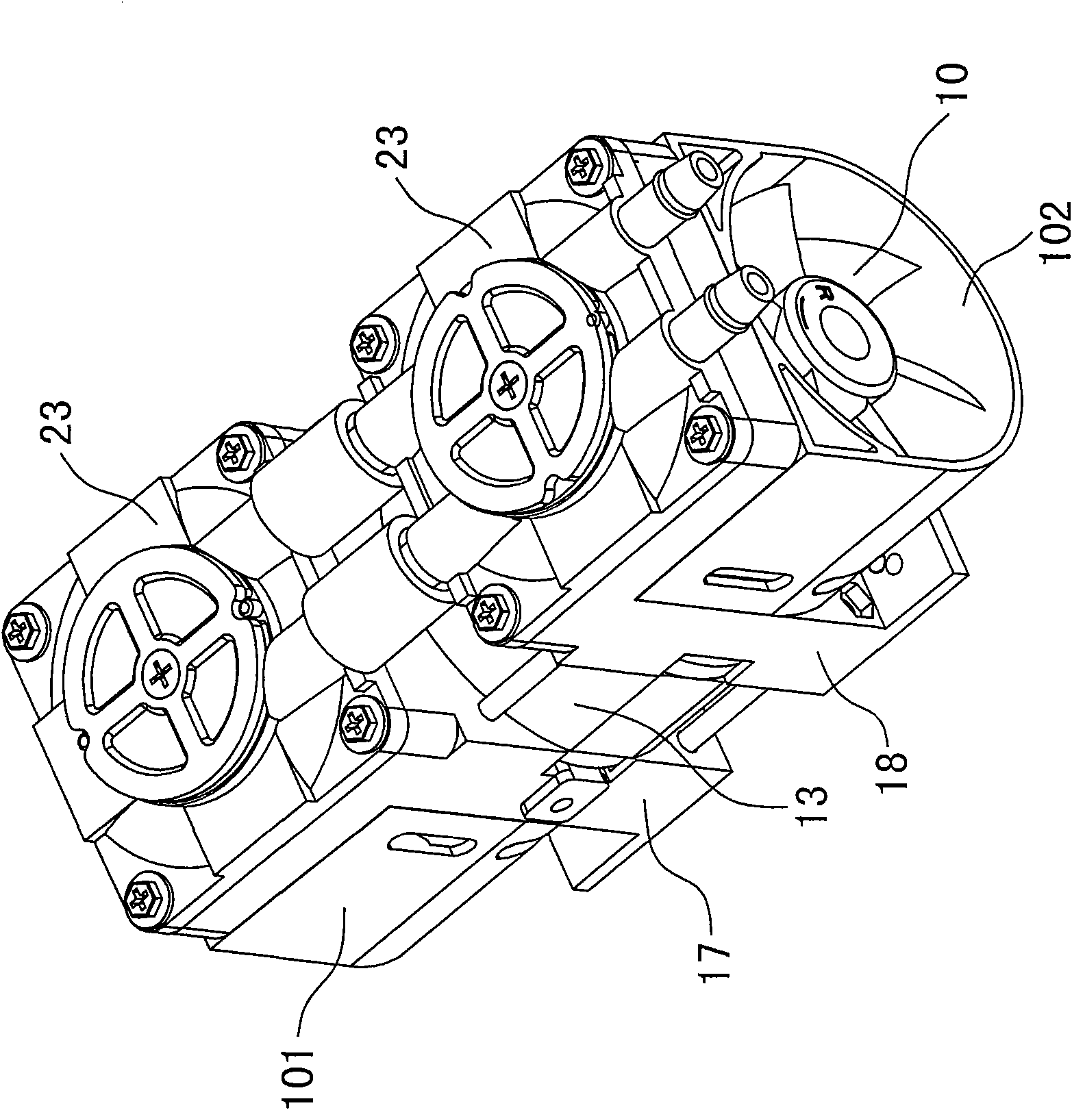
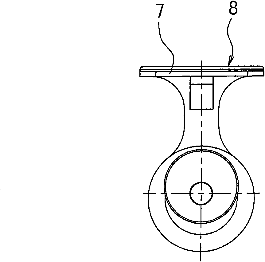
[0011] The invention discloses an energy-saving and noise-reducing vacuum pump, such as figure 1 , figure 2 As shown, it includes a motor (the motor is composed of a stator 13, a rotor 14, a motor shaft 11, and left and right mounting brackets 17, 18), a motor casing, a pump body and a pump cover, and the two ends of the motor shaft 11 are respectively connected to the left and right pull rods 7, 8, the heads of the left and right pull rods 7, 8 are fixedly connected with the film pressing piece 3 and extend into the left and right pump chambers 21, 22, and a diaphragm 4 is installed between the head of the left and right pulling rods and the membrane pressing piece 3, It is characterized in that eccentric wheels 5 and 6 are respectively installed between the two ends of the motor shaft 11 and the left and right pull rods 7 and 8 . The vacuum pumps in the prior art are directly installed with left and right pull rods 7' and 8' at the two ends of the motor shaft. After assem...


PUM


Abstract

The invention relates to an energy-saving and noise-reducing vacuum pump, which comprises a motor, a motor shell, a pump body and a pump cover, wherein both ends of a motor shaft are connected with a left pull rod and a right pull rod respectively; the head parts of the left pull rod and the right pull rod are fixedly connected with a film pressing piece and stretch into a left pump chamber and a right pump chamber; and a membrane is arranged between the head parts of the left pull rod and the right pull rod and the film pressing piece. The vacuum pump is characterized in that eccentric wheels are arranged between both ends of the motor shaft and the left pull rod and the right pull rod respectively. After the balance weight of the eccentric wheels is increased, the vacuum pump runs steadily during working, and the deflection phenomena can be avoided. The moving phase of the two pull rods is guaranteed to be 180 degrees so as to reduce various mechanical noises caused by gaps such as the gap between the motor shaft and a motor bearing, the gap between the motor bearing and a motor end cover, the gap between the eccentric wheels and the bearing, the gap between the bearing and the pull rods, and the like, and the mechanical noise is controlled to be below 45 decibels so as to meet the requirements on the noise of household appliances.

Description

technical field [0001] The invention relates to a vacuum pump, in particular to an energy-saving and noise-reducing vacuum pump. Background technique [0002] The vacuum pump is mainly composed of a motor and a vacuum pump body. The existing oil-free vacuum pump can be divided into two types: diaphragm oil-free vacuum pump and piston oil-free vacuum pump, and can be divided into single pump chamber and double pump chamber. The gas paths of the pump chambers are connected in series. For example, the diaphragm type double pump chamber air circuit parallel vacuum pump, the motor and the vacuum pump chamber are fixedly connected by screws, which are mainly used in industrial equipment and household appliances. The work of the vacuum pump chamber is that the circular motion of the motor is transformed into a diaphragm through the eccentric wheel. Reciprocating motion, the shortcomings of the existing technology: first, because the vacuum pump assembly is repeated assembly, and ...

Claims


Application Information

Patent Timeline
Patent Type & Authority Applications(China)
IPC IPC(8): F04B53/00F04B45/047F04B43/04
Inventor 周纪昌
Owner 周纪昌
Why Eureka
Try Eureka