Grounding test apparatus of reversely connected flow ratio device high voltage bridge based on cable insulation technique

A cable insulation and test device technology, applied in the direction of measurement device, voltage/current isolation, resistance/reactance/impedance measurement, etc., can solve the problems of easy electric shock, large working voltage limitation, difficulty in insulation, etc., and achieve the effect of good insulation characteristics

Inactive Publication Date: 2009-09-09
HARBIN UNIV OF SCI & TECH
View PDF0 Cites 1 Cited by
  • Summary
  • Abstract
  • Description
  • Claims
  • Application Information

AI Technical Summary

Problems solved by technology

[0003] The present invention proposes to solve the problems of large operating voltage limitation, difficulty in insulating the high-voltage coil and connected devices from the ground (cabinet) and easy electric shock

Method used


Image

  • Grounding test apparatus of reversely connected flow ratio device high voltage bridge based on cable insulation technique
  • Grounding test apparatus of reversely connected flow ratio device high voltage bridge based on cable insulation technique
  • Grounding test apparatus of reversely connected flow ratio device high voltage bridge based on cable insulation technique

Examples


specific Embodiment approach 1

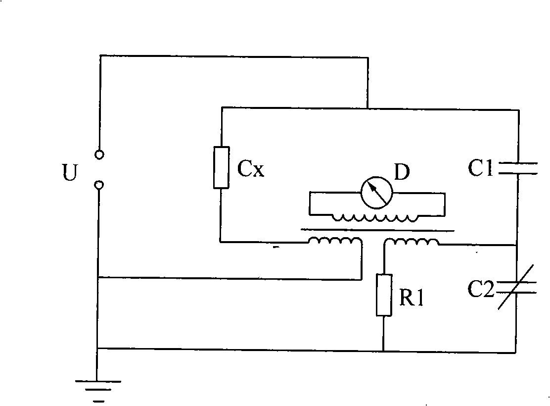
[0008] Specific implementation mode one: combine figure 1 Describe this embodiment, this embodiment comprises passive current ratio device electric bridge and lead wire cable 1, passive current ratio device electric bridge is made up of power transformer 1-3, first standard capacitor C1, first resistance R1, second adjustable capacitor C2 1. The detection transformer 1-4 of the primary side with adjustable turns and the balance indicator D are composed; One end of the standard capacitor C1 is connected to the ground wire; the other end of the first standard capacitor C1 is respectively connected to one end of the first resistor R1 and one end of the second adjustable capacitor C2; the other end of the second adjustable capacitor C2 is connected to the ground wire ; The other end of the first resistance R1 is connected with one end of the primary side of the detection transformer 1-4 with the primary side of the adjustable number of turns, and the other end of the primary side ...

specific Embodiment approach 2

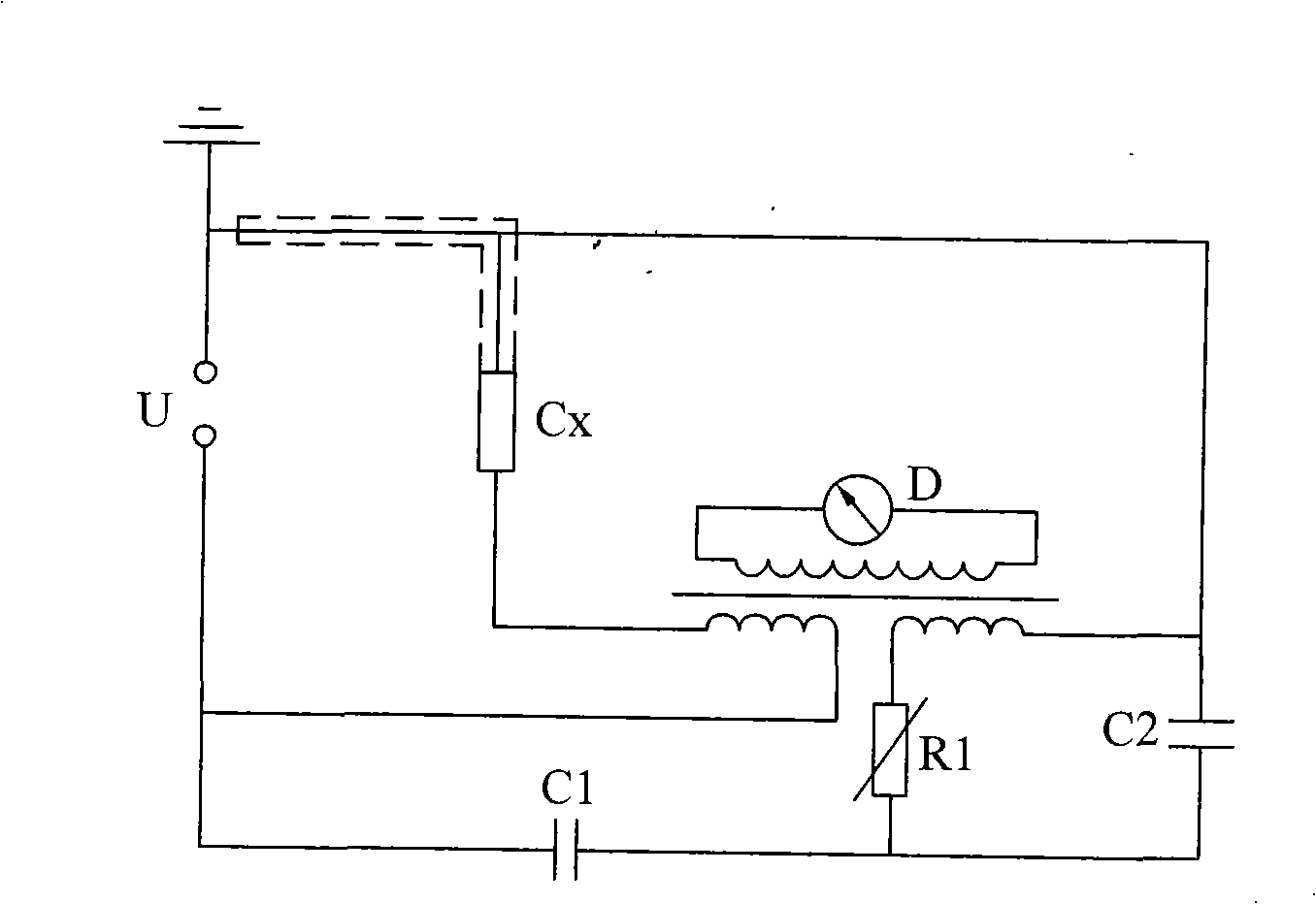
[0009] Specific implementation mode two: combination figure 1 , image 3 This embodiment is described. The difference between this embodiment and the first embodiment is that the outer shielding layer 1 - 1 of the lead cable 1 is connected to the ground wire at the high voltage end of the lead cable 1 . Other compositions and connection methods are the same as those in Embodiment 1. The purpose of the outer shielding layer 1-1 being grounded at one end of the high-voltage end of the lead cable 1 is to eliminate the influence of the lead cable 1 to ground capacitance and leakage conductance on the measurement of the test object. The current flowing through the ground capacitance and leakage conduction of the lead cable 1 flows in from its core and returns from its outer shielding layer 1-1, so there is no magnetic flux inside the iron core of the current ratio meter, only the test flow through the iron core Product current generates magnetic flux to participate in bridge bala...

specific Embodiment approach 3

[0010] Specific implementation mode three: combination Figure 4 , Figure 5 This embodiment is described. The difference between this embodiment and the first or second embodiment is that the terminal of the lead cable 1 adopts a wrapped terminal or a cold-shrinkable terminal. Other compositions and connection modes are the same as those in Embodiment 1 or 2. The wrapped terminal is mainly used in the test of the test product with a voltage level below 10kV; the cold shrinkable terminal is mainly used in the test of the test product with a voltage level above 10kV.


PUM


Abstract

A grounding test apparatus of reversely connected flow ratio device high voltage bridge based on a cable insulation technique relates to the test apparatus. The invention is proposed to solve the problem that the present flow ratio device capacitance bridge is largely limited in working voltage, difficult in ground insulation and liable to cause electric shock when testing a grounding tested object. Both a passive flow ratio device bridge and an active flow ratio device bridge use a leader cable which is a high-voltage coaxial cable; the high voltage end of the leader cable is connected with a high voltage leading-out wire and the tested object end of the leader cable is connected with the grounding tested object. The high-voltage coaxial cable has excellent insulating property and can isolate the high voltage from a case body and other devices therein, complex ground insulation is unnecessary, and no accident of the electric shock takes place during high voltage test; the terminal of the leader cable employs two terminals including a taped terminal and a cold-shrinkage terminal, thus eliminating the limit of the working voltage, and simultaneously providing a new test apparatus that replaces the traditional reversely connected, diagonally-grounded Schering bridge for the test of the grounding tested object. The invention can be applied to passive and active balanced bridges.

Description

technical field [0001] The invention relates to a test device, in particular to a test device for a grounded sample. Background technique [0002] The capacitance value and loss factor of electrical equipment insulation are generally tested by the bridge method, and the commonly used bridges include resistance-capacitance bridges and transformer bridges. For long cables, power capacitors and other large-capacitance grounding test products, the Xilin bridge with a resistance shunt is generally used for measurement. The easiest way is to connect the ground terminal to the high-impedance bridge arm of the Xilin bridge, so that the adjustable bridge arm of the bridge is on the high-voltage side. In order to ensure the safety of the operator, it is necessary to install the adjustable bridge arm of the bridge in a Faraday cage, and the potential of the person in the cage is close to the potential of the adjustable bridge arm to ensure safety. The other is the diagonal connection...

Claims


Application Information

Patent Timeline
IPC IPC(8): G01R27/26G01R15/14
Inventor 李忠华郑新龙郑欢
Owner HARBIN UNIV OF SCI & TECH
Why Eureka
Try Eureka