Ultrasonic probe, backing material for ultrasonic probe, and method of manufacturing the same

Inactive Publication Date: 2008-12-11
FUJIFILM CORP
View PDF1 Cites 15 Cited by
  • Summary
  • Abstract
  • Description
  • Claims
  • Application Information

AI Technical Summary

Benefits of technology

[0022]According to the present invention, by dispersing the composite powder, which is formed by covering surfaces of powder of a material having a larger acoustic impedance than that of the parent material with the insulation coating of oxide, to fil

Problems solved by technology

If the backing material has poor acoustic characteristics, it cannot sufficiently absorb unwanted ultrasonic waves but may cause degradation of image quality of ultrasonic waves.
Further, when plural vibrators are one-dimensionally or two-dimensionally arranged in an arrayed structure, the wiring becomes complicated.
In this case, if the backing material has conductivity, the wiring may be shorted or noise may be mixed.
Further, the acoustic matching layer matches the acoustic impedance of the vibrators with the acoustic impedance of a human body or the like and reduces the reflection of ultrasonic waves.
However, if only rubber is used, the acoustic impedance of the backing material becomes as small as about 1MRayl because the rubber

Method used


Image

  • Ultrasonic probe, backing material for ultrasonic probe, and method of manufacturing the same
  • Ultrasonic probe, backing material for ultrasonic probe, and method of manufacturing the same
  • Ultrasonic probe, backing material for ultrasonic probe, and method of manufacturing the same

Examples


Embodiment Construction

[0032]Hereinafter, preferred embodiments of the present invention will be explained in detail with reference to the drawings. The same reference numerals will be assigned to the same component elements and the description thereof will be omitted.

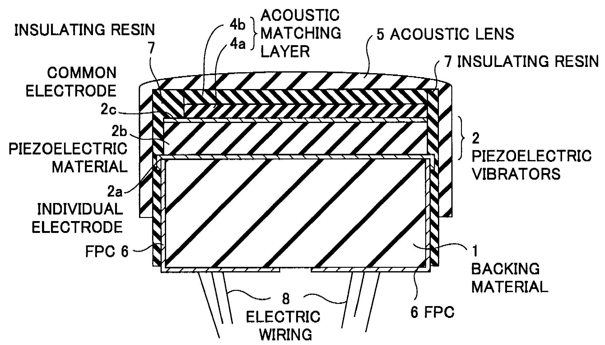
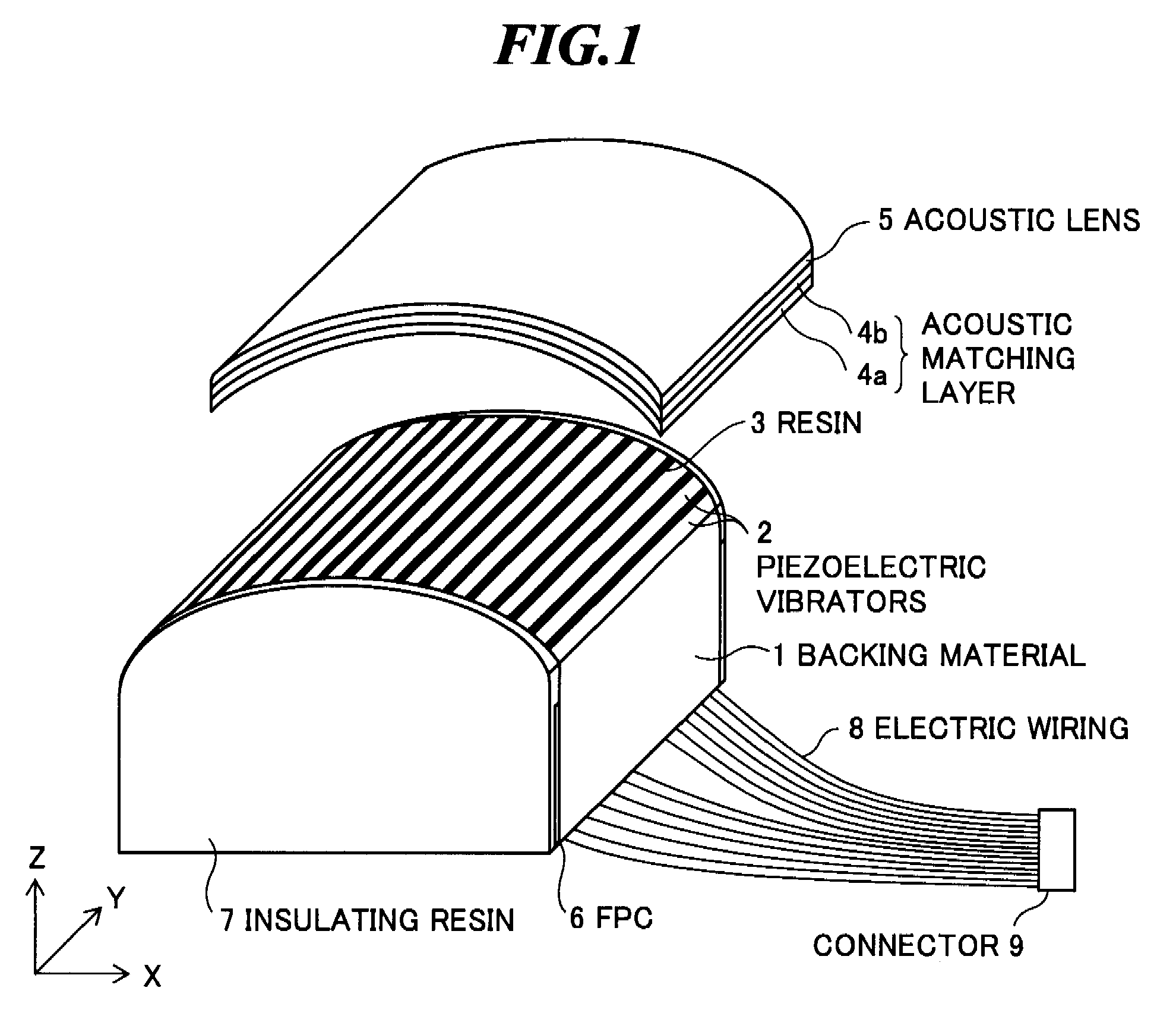
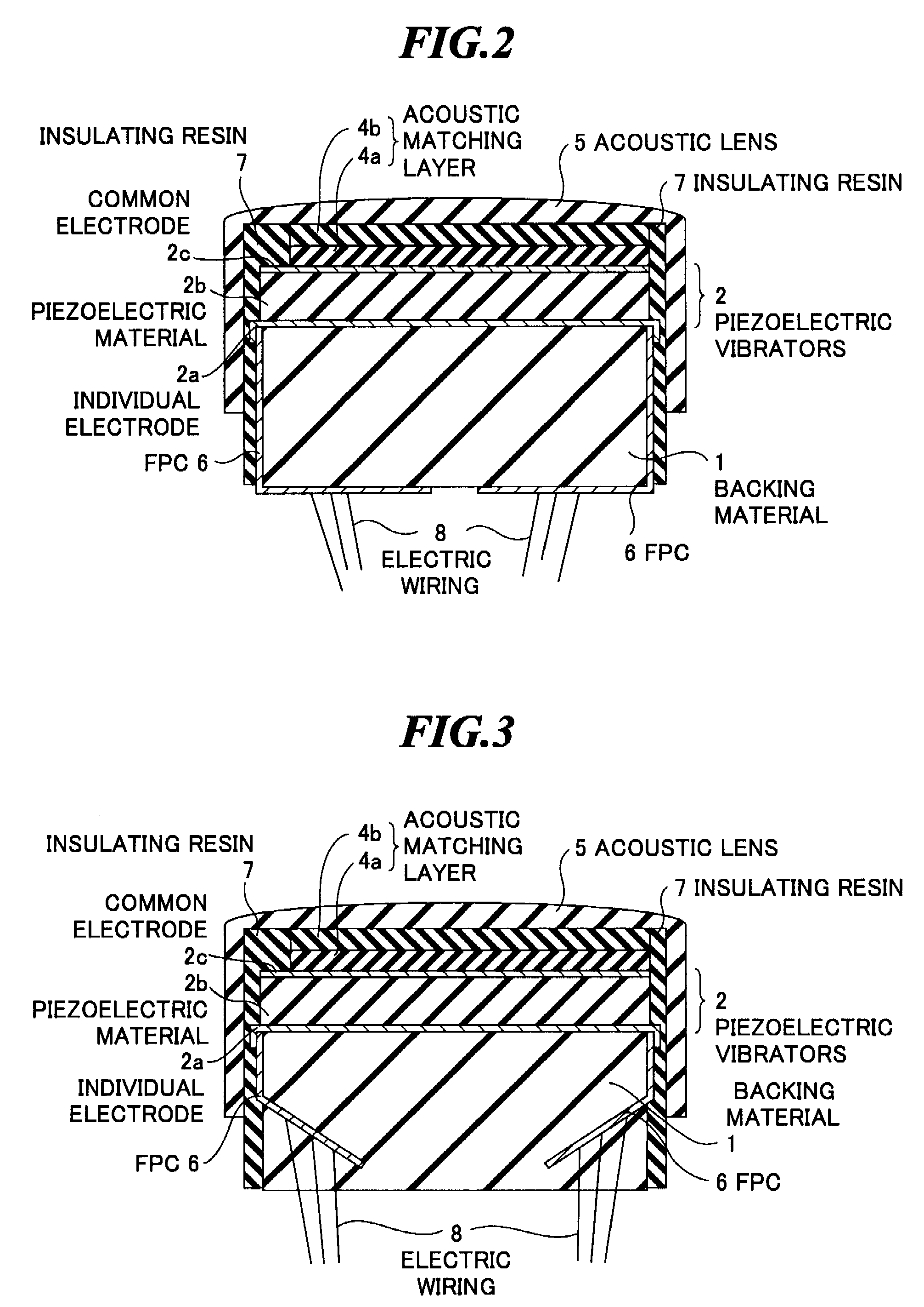
[0033]FIG. 1 is a perspective view schematically showing an internal structure of an ultrasonic probe according to one embodiment of the present invention, and FIG. 2 is a sectional view of the internal structure of the ultrasonic probe shown in FIG. 1 along a plane in parallel with the YZ-plane. Here, a convex one-dimensional array probe to be used in an ultrasonic endoscope will be explained as an example, but the present invention may be applied to a probe having a single vibrator or one-dimensional or two-dimensional array probe in another form.

[0034]As shown in FIGS. 1 and 2, the ultrasonic probe has a backing material 1 having a shape convex upward, plural ultrasonic transducers (piezoelectric vibrators) 2 one-dimensionally arranged on...


PUM

PropertyMeasurementUnit
Thicknessaaaaaaaaaa

Abstract

A backing material that is advantageous in insulation property and can realize a desired acoustic impedance without making the cross-linking and curing reaction of elastomer or resin as a parent material unstable. The backing material is provided on a backside of vibrators for transmitting and/or receiving ultrasonic waves in an ultrasonic probe, and the backing material includes: a parent material containing elastomer or resin and having an insulation property; and composite powder dispersed to fill the parent material, and the composite powder includes powder of a material having a larger acoustic impedance than that of the parent material and an insulation coating for covering a surface of the powder, and the insulation coating contains an oxide of an element of group XIII to group XV except for carbon (C), nitrogen (N), phosphorus (P).

Description

BACKGROUND OF THE INVENTION[0001]1. Field of the Invention[0002]The present invention relates to an ultrasonic probe to be used for transmitting and receiving ultrasonic waves in an ultrasonic diagnostic apparatus. The present invention further relates to a backing material to be used for absorbing unwanted ultrasonic waves in the ultrasonic probe, and a method of manufacturing the backing material.[0003]2. Description of a Related Art[0004]An ultrasonic diagnostic apparatus transmits ultrasonic waves to an object to be inspected such as a human body or structure and receives ultrasonic echoes reflected from the object by using an ultrasonic probe, and displays images based on detection signals of ultrasonic waves. Thereby, examinations of organs and blood vessels within a body and nondestructive inspections within a structure are performed.[0005]In the ultrasonic probe, as an ultrasonic transducer for transmitting and / or receiving ultrasonic waves, a vibrator (piezoelectric vibrato...

Claims


Application Information

Patent Timeline
IPC IPC(8): H04R17/00C08K3/22B05D7/00A61B8/00
CPCC08K3/22
Inventor YUUYA, SHIGENORINAKAMURA, TAKASHI
Owner FUJIFILM CORP
Why Eureka
Try Eureka